14
The stimulator body (1) contains the receiver coil and electronics. The coil converts
the signal from the external Antenna into an electrical current, which both powers
and controls the Implant.
The cable (3) consists of eight individual metal wires, coiled in two bundles of
four. The wires are individually coated with ETFE (Teon), and the two bundles
are inserted into a dual-lumen silicone tube. This design allows the cable to stretch
slightly and makes it resistant to exion and extension.
The cu electrode (2) is a silicone cu, 23 mm long with 12 platinum/iridium con-
tact discs located on the inside. These discs form the electrical contact to the nerve.
The electrode contacts are organized as four sets of three, each triplet making up
one channel. The four channels are distributed evenly around the nerve, in order to
allow selective stimulation of dierent fascicles inside the nerve.
6.2 The ActiGait®
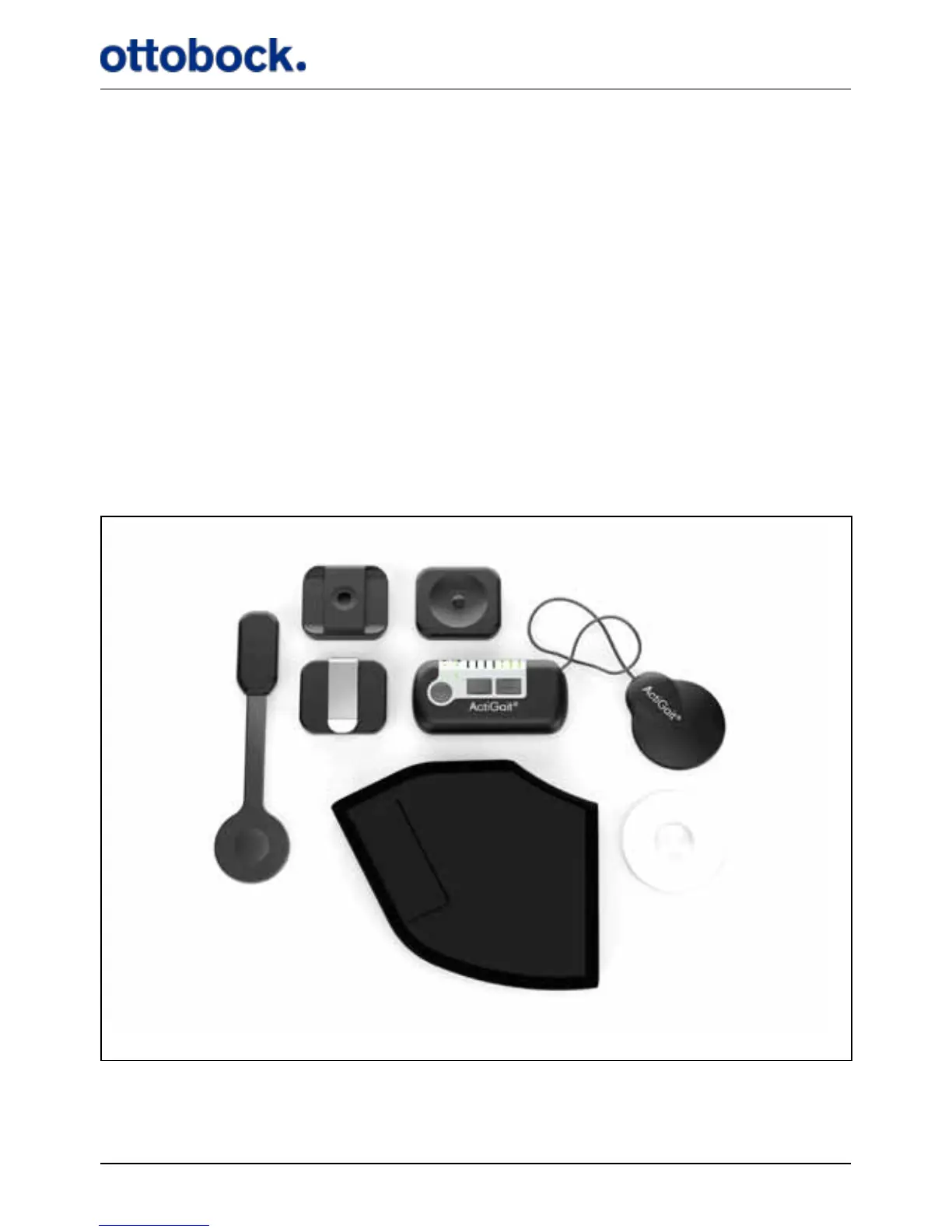
The ActiGait® consists of the Heel Switch (1), the Belt Loop (2), the Body Clip (3),
the Belt Clip (4), the Control Unit (5), the Antenna (6), the Heel Sock (7) and the
Antenna Fixture (8) (see Figure 3).
1
7
3
8
54
2
Figure 3: The ActiGait®. 1: Heel Switch, 2: Belt Loop, 3: Body Clip, 4: Belt Clip, 5: Control Unit, 6: An-
tenna, 7: Heel Sock, 8: Antenna Fixture
6