81
Changing the rear wheel position can also change the angle of the caster axle in
relation to the ground. Ensure that this angle is always approx. wide. The wheel lock must
be re-adjusted as well.
Make sure to rmly retighten all screws and nuts after making adjustments. The torque
for the screws (Fig. 58, item A) is .
58
A
B
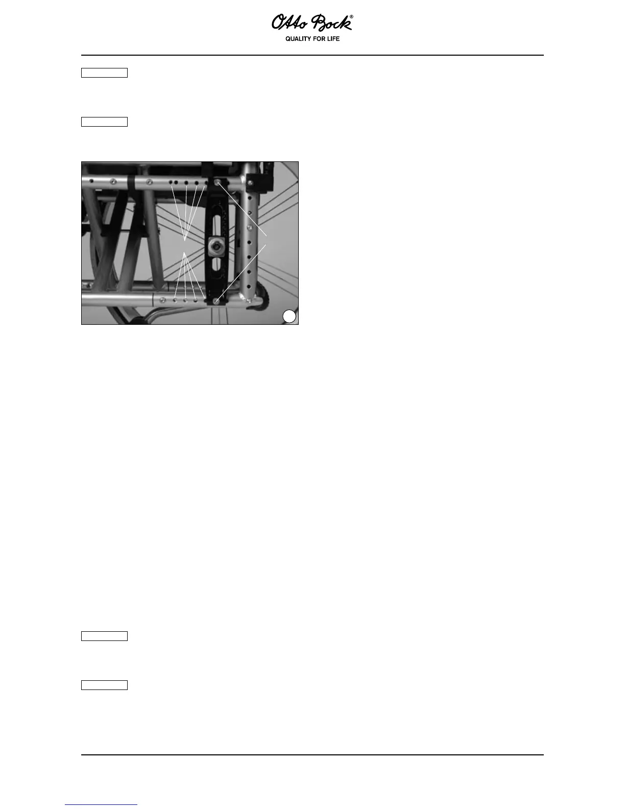
6.3 Changing the Rear Wheel Position in the Rear Wheel Adapter (Fig. 59–61)
Each change of position of the quick-release axle housing in the rear wheel adapter has an inu-
ence on the posterior seat height and the centre of gravity! The relation of anterior and posterior
seat height represents the individual seat inclination. The higher you attach the rear wheel in the
rear wheel adapter, the more the seat pitches down. This has two effects:
1. The wheelchair has a greater tendency to tilt backwards.
2. The user sits deeper in the wheelchair and thus has more stability.
(Fig. 59)
Loosen the nut (Fig. 59, item A) of the quick-release axle housing (Fig. 59, item B) on the inside
of the frame, until the tapered washers can be spread apart slightly. Now you can move the
quick-release axle housing with nuts and tapered washers into the desired position.
Let the lugs of the tapered washers engage in the new desired orientation and rmly re-tighten the
nut (Fig. 59, item A). Make sure that the position of the tapered camber washers is not changed
and that both the left and right rear wheel attachment devices are set in the same vertical position.
The distance between the rear wheel and side panel can now be continuously adjusted by ad-
justing the rear wheel tting (Fig. 59, item C).
When the rear wheel position is changed, the angle of the caster axle in relation to
the ground also changes. Ensure that this angle is always approx. 90° wide. The wheel lock
must be re-adjusted as well.
Make sure to rmly retighten all screws and nuts after making adjustments. The torque
for the hexagon nuts (Fig. 59, item A/C) is .
 Loading...