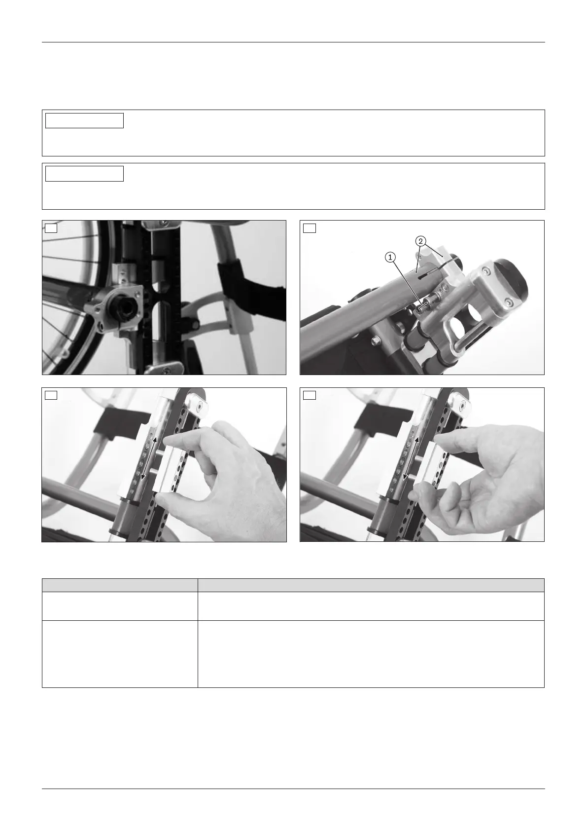
6) Tighten the Allen head screws on each perforated plate from the inside to 10Nm (see fig.6, item 1).
→ Once changed, the clamping flanges on the left and right must both have the same vertical position on the
slider.
7) Put the wheels back on.
INFORMATION
Following adjustment, the track of the drive wheel, the caster journal angle and the knee lever wheel lock must be
checked and, if necessary, readjusted (refer to the corresponding section).
INFORMATION
By disassembling and turning the perforated plate in the "long" shock absorber, additional height adjustments
can be implemented. For information on disassembly/assembly, see the 647G829 service manual.
5 6
7 8
6.2.3 Adjusting the drive wheel camber
Position of drive wheel Effects
0° position
• Narrow track, excellent straight-line stability
• Low rolling resistance
Wheel camber
• Wheelchair becomes more manoeuvrable, turns faster and tips less easily
to the side
• The wheel position protects the hands when turning the handrim
• Overall width increases
• Increased rolling resistance
6.2.3.1 Adjusting the 0°/3°/6°/9° drive wheel camber
The modular system of the product offers camber options for different sloped settings of the drive wheels (0° and
3°: see fig.9, item 1; 6° and 9°: see fig.9, item2).
1) Remove the wheels.
2) Place the wheelchair upside down.
11Ventus
Settings



 To Next Page