INFORMATION
Changing the drive wheel position can also change the angle between the caster wheel journal and the ground.
However, this must always be approx. 90° and thus readjusted accordingly. The knee lever wheel lock also has
to be readjusted.
6.2.1 Adjusting the depth of the drive wheels
The horizontal drive wheel position is changed by moving the slider on the frame horizontally. This has the following
effects:
Position of drive wheel Effects
Move backwards (passive setting)
• Larger wheelbase
• Larger turning circle
• Greater stability of the wheelchair
• Wheelchair is harder to tip backwards when crossing obstacles
• Position recommended for inexperienced users
Move forwards (active setting)
• Smaller wheelbase
• Less load on caster wheels = greater manoeuvrability
• Less stability of the wheelchair
• Wheelchair is easier to tip backwards when crossing obstacles
INFORMATION: An anti-tipper should be installed if necessary.
• Setting recommended only for experienced users
6.2.1.1 Adjusting the sliders on the frame
The sliders can be moved continuously in a horizontal direction along the frame tube. To facilitate adjustment the
frame has a grid with 9 positions (see fig.65).
1) Remove the wheels.
2) Place the wheelchair upside down.
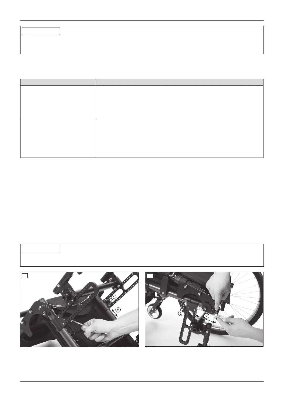
3) Loosen the 2 x 2 Allen head screws on the sliders under the seat bottom (see fig.1, item1).
4) Move the sliders with the axle unit to the desired position (see fig.1, item2):
→ Use the grid as a rough guide (see fig.2, item1).
→ For a more accurate guide, measure the distance between the end of the tube and the outer edge of the
slider (see fig.2, item2).
5) Ensure that the depth setting is the same. Once changed, the left and right sliders must both have exactly the
same horizontal position on the frame.
6) Tighten the Allen head screws to 10Nm (see fig.1, item1).
INFORMATION
Following adjustment, the track of the rear wheel, the caster journal angle and the knee lever wheel lock must be
checked and, if necessary, readjusted (refer to the corresponding section).
1 2
6.2.1.2 Adjusting sliders with shock absorber system
Adjustment is done in the same way as for sliders without a shock absorber system.
9Ventus
Settings