OWC Data Doubler Installation
36
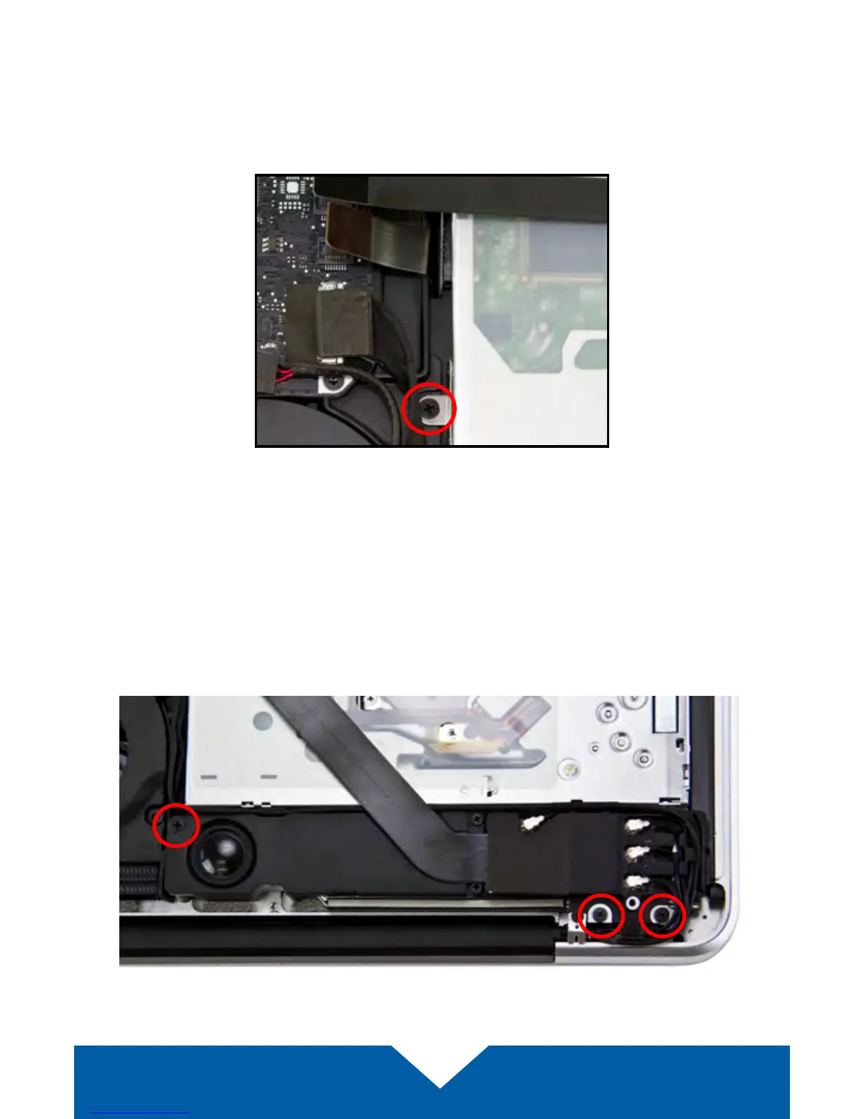
7. Near the left edge of the optical drive, between the fan and the ribbon
cables there is a metal bracket that is attached to the optical drive with
a small Phillips screw (highlighted below in red). Remove the screw; be
careful to not damage the cable that is between the logic board and the
optical drive. This screw will be used again during the reassembly process.
8. Below the optical drive there is a speaker housing that is held in place by
three Phillips screws; remove them. Once the screws are removed, gently
lift up on the speaker housing to dislodge it from its mounting posts. The
speaker’s cable should remain connected. The left-most screw is shorter
than the other two and will need to be axed in the same location later. All
three screws will be used again during the reassembly process.