OWC Data Doubler Installation
67
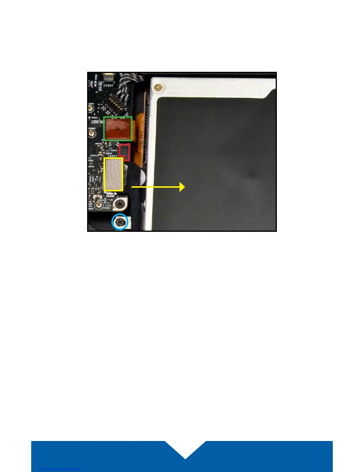
8. Near the left edge of the optical drive, there are two cables and a small
plastic retainer that need to be disconnected from the logic board before
you can proceed. First, use a corner of the included nylon pry tool to gently
dislodge the small plastic retainer. Highlighted in red, the intact retainer is
partly obscured in this photo.
9. Next, remove the black cable with the silver connector (highlighted in
yellow) by gently pushing the connector in the direction shown above, until
it disconnects from the logic board.
10. In many cases, the black cable will obscure a small black Phillips screw
(shown above in blue). This screw is connected to a metal bracket that
helps to hold the optical drive in place. Remove the screw and set it aside;
it will be used during reassembly.
11. Just above the spot where the silver connector was attached to the logic
board in Step 9, there is an orange ribbon cable. Note: this cable may
be black in some cases. The cable connects the optical drive to the logic
board. Use the nylon pry tool to gently lift the ribbon cable’s connector o
the logic board. Caution: this cable is easily damaged.
 Loading...