Do you have a question about the Pack Leader ELF-50 and is the answer not in the manual?
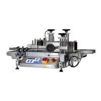
Diagram showing main components of the labeling machine.
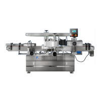
Diagrams illustrating the physical dimensions of the labeling machine.
Instructions and warnings for safe operation before starting the machine.
Guidelines and warnings for safely interacting with the control panel.
Step-by-step guide for loading labels into the applicator.
Guide for adjusting the label sensor sensitivity for accurate placement.
Explanation and adjustment of the object sensor for bottle detection.
Overview and function of the machine's control panel interface.
Step-by-step instructions for operating the machine before starting.
Guide to configuring settings like pre-count and label delay on the control panel.
Schematic of the machine's electrical system and wiring.
Detailed exploded view of the applicator assembly components.
Exploded view of the applicator's motor assembly and its parts.
Exploded view of the base paper collection mechanism.
Exploded view of the label peel plate assembly.
Exploded view of the applicator driving assembly.
Exploded view of the bearing seat fixing plate assembly.
Exploded view of the PU roller assembly.
Exploded view of the aluminum knurled roller assembly.
Exploded view of the label supply assembly.
Exploded view of the label supply plate assembly.
Exploded view of the tension bar assembly.
Exploded view of the label roller assembly.
Exploded view of the label sensor base assembly.
Exploded view of the label load assembly without a printer.
Exploded view of the label press assembly.
Exploded view of the label press roller assembly.
Exploded view of the applicator adjustment assembly.
Exploded view of the main wrap station assembly.
Exploded view of the wrap station's motor assembly.
Exploded view of the wrap station's driving pulley mechanism.
Exploded view of the wrap station's driven pulley mechanism.
Exploded view of Space Roller Assembly 1.
Exploded view of Space Roller Assembly 2.
Exploded view of the wrap station up/down adjustment assembly.
Exploded view of the pressure plate assembly.
Exploded view of the pressure plate adjustment mechanism.
Exploded view of the conveyor system.
Exploded view of the conveyor's motor assembly.
Exploded view of the conveyor's driving pulley assembly.
Exploded view of the conveyor's driven pulley assembly.
Exploded view of the foot stand assembly.
Exploded view of the in-feed turntable assembly.
Exploded view of the in-feed cabinet assembly.
Exploded view of the in-feed guide rail assembly.
Exploded view of the turntable's base assembly.
Exploded view of the out-feed turntable assembly.
Exploded view of the out-feed cabinet assembly.
Exploded view of the out-feed guide rail assembly.
Exploded view of the out-feed holder assembly.
| Weight Capacity | 50 kg |
|---|---|
| Power Source | Electric |
| Frequency | 50/60 Hz |
| Voltage | 220V |
| Operating Temperature | 40°C |