User Manual Chapter 1
GFK-2749A Jan 2020
PSM Module Description and Specifications 6
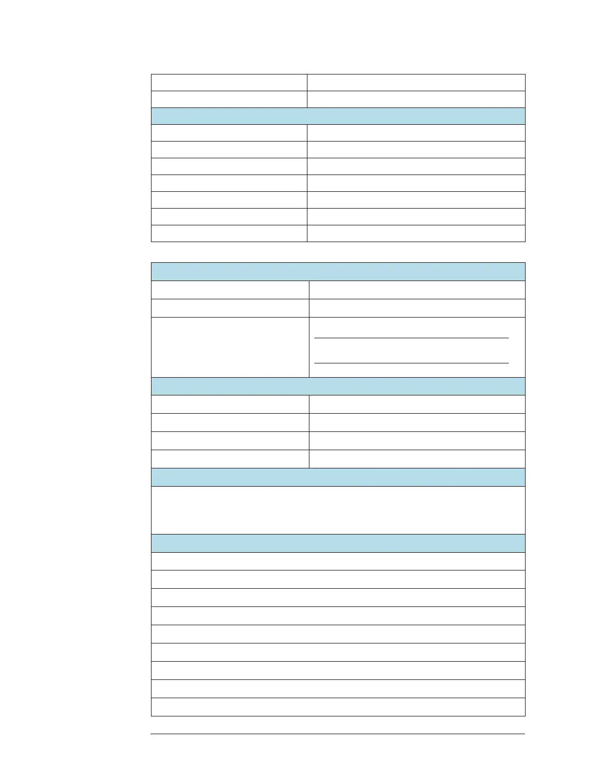
Phase difference between grids:
0.2% of Full Scale (see page 52)
0.2% of Full Scale (see page 51)
Terminal Assembly Input Terminal Ratings
15 Amps continuous maximum
150 VAC/VDC at 1 Amp Resistive, maximum
Note: Actual contact ratings depend on load
type. See “Sync Relay contacts” on page 5.
RX3i CPU Memory Requirement for Automatic Data Exchange
Data Exchange Time Between RX3i CPU and PSM
A complete data exchange between the PSM and RX3i occurs during each controller scan.
Minimum scan time is 3.5ms per PSM module in the backplane. Minimum data update rate is one
power line period. See “System Operation” on page 7 and “PSM Status Flags” in Chapter 3:.
ANSI Protective Functions
ANSI 25 – Generator and Public Grid Synchronization
ANSI 27 – Under-voltage Protection
ANSI 32 – Reverse Power Protection
ANSI 47 – Voltage Phase Sequence Protection
ANSI 50 – Instantaneous Over-current Protection
ANSI 59 – Over-voltage Protection
ANSI 60 – Voltage (Current) Imbalance Protection
ANSI 81U – Under-frequency Protection
ANSI 81O – Over-frequency Protection