User Manual Chapter 3
GFK-2749A Jan 2020
Configuration and Data Transfer 57
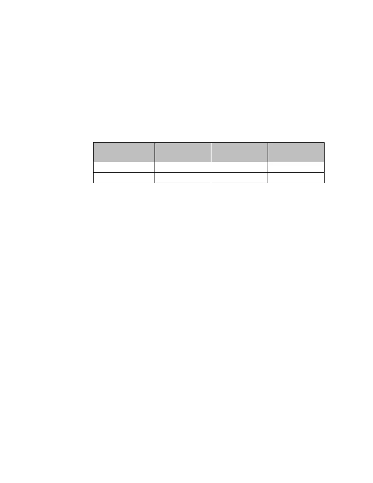
Absolute Maximum (Full Scale) Readings
The peak values that the PSM system is capable of reading are detailed below. Applying
higher voltages than 1064.9V on the high voltage range, or 212.4V on the low voltage range
(peak value) or higher currents than 10.652A (peak value) to the PSM Interface Module will
lead to the erroneous results. Such a situation will be accompanied by the appropriate fault
bits (FaultXX and ClampedInput) in the %I status bits being set to 1 with the LED “FLT”
flashing or steady red. These are the Full-Scale values for their respective ranges and are
used as the basis for the accuracies in chapter 1, Specifications. Extended operation at or
above the peak values may shorten the mean time between failure (MTBF) of the PSM
system.
3.3 Example Configurations
A portion of the PSM configuration is downloaded with the PAC Machine Edition hardware
configuration (see “Configuration Parameters” on page 33). The remaining details must be
set, in the form of %Q bits, in application logic when the PLC goes to run mode. Below are
example configurations for typical applications.
Configuration for 120/240 VAC Single Phase System 57
Configuration for 600VAC Single Phase System 60
Configuration for 120/208 WYE Three-Phase Four-Wire System 62
Configuration for 120/208 3-Wire Delta system with Two PTs (Two Wattmeter Method),
B-Common. 64
Configuration for 120/208 3-Wire Delta system with Two PTs (Two Wattmeter Method),
C-Common 66
Configuration for 120/208 4-Wire WYE Synchro/Power Control Connection 71
Configuration for 480V 4-Wire WYE Synchro/Power Control Connection 74
3.3.1 Configuration for 120/240 VAC Single Phase System
The following shows a typical hardware configuration for a signal phase, 3-wire power
monitoring application. This example shows settings for Grid 1; all the settings can be
applied to the respective Grid 2 parameters. Note that the offset and gain values were found
on the IC694PSM001 module faceplate label and on the IC694ACC200 terminal
assembly label. Note that the 120V range will accurately measure voltages slightly above
120VAC RMS. In the example below, 125VAC RMS is chosen as the nominal voltage.
The Nominal Voltage is the anticipated Phase-to-Neutral voltage in the single-phase
configuration.