User Manual Chapter 1
GFK-2749A Jan 2020
PSM Module Description and Specifications 7
Power Measurement Configurations
Four-wire three phase wye systems: 3 PTs and 3 CTs plus Neutral CT (optional)
Three-wire three phase delta systems: 2 PTs and 2 CTs
Three independent single phase systems: 1 PT and 1 CT for each phase
Three-wire single phase systems: 120/240 (2 PTs and 2 CTs)
Required. PSM module and Terminal Assembly must be
installed in a NEMA/UL Type 1 enclosure or an IP20
rating providing at least a pollution degree 2
environment.
When this system is installed in an area designated as
Class 1 Zone 2 in Europe, compliance with the ATEX
Directive requires an enclosure with a minimum rating
of IP54.
1.8 System Operation
The PSM digitizes the voltage and current input waveforms from Grid 1 and Grid 2, storing
the results into internal memory buffers. Data is updated every power line cycle.
Therefore, the data is updated every 20ms on a 50Hz power grid, or every 16.67ms on a
60Hz power grid.
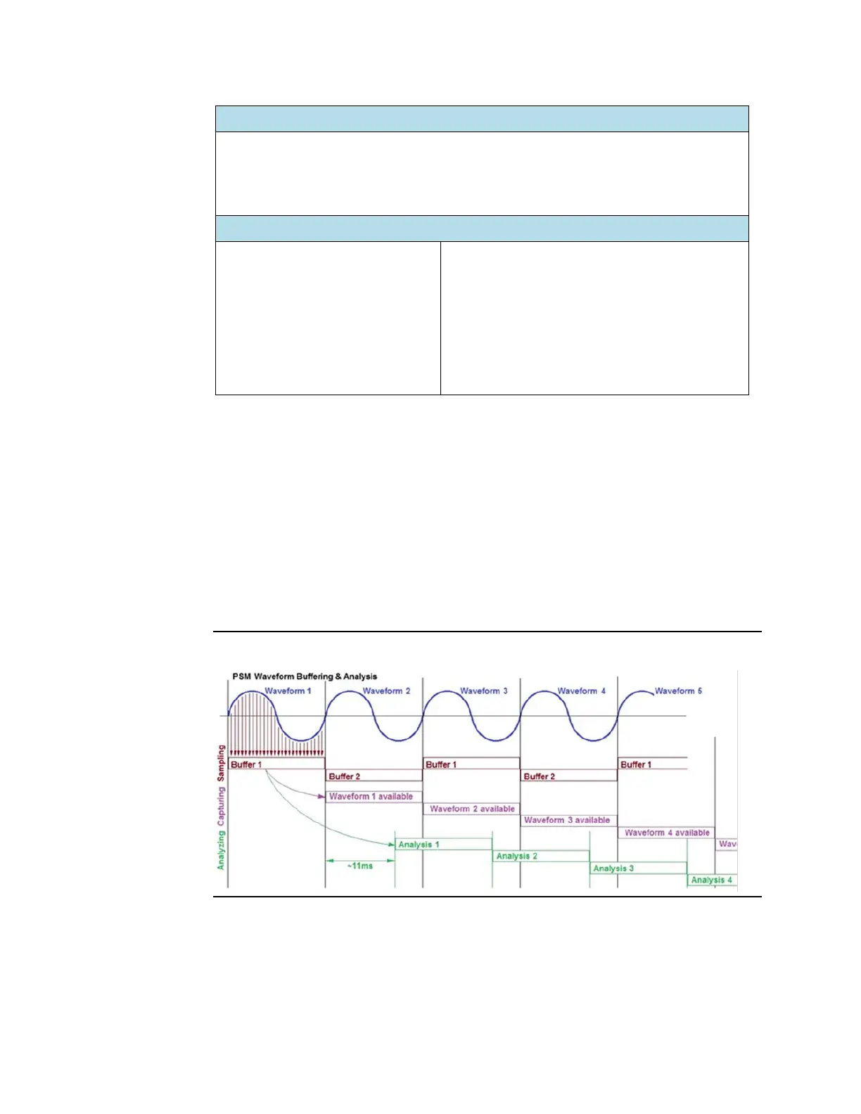
While background processes analyze a set of waveforms stored in one memory buffer, the
next set of waveforms is captured and stored in another buffer. In this way, calculations are
performed on each waveform with the DSP processing the data in about two-thirds of a
power line cycle.
Figure 3