User Manual Chapter 2
GFK-2749A Jan 2020
Installation 23
Note: The following information is supplied only for diagnostics (making continuity checks of the
cable):
These cables have straight through connections (pin 1 connects to pin 1; pin 2 connects to
pin 2, etc.). The cables are twisted-pair type, connected to minimize noise and crosstalk
between signals.
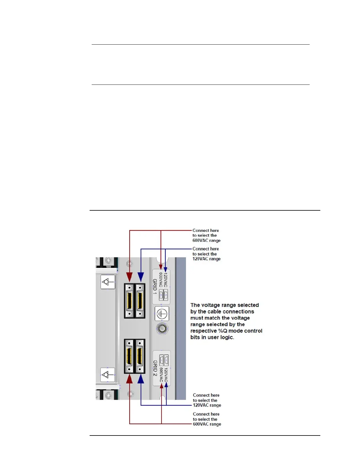
Voltage Range Selection
The voltage range of each grid can be selected independently. Note that the PSM
ConnectionOK status bit is only meaningful when both grids are used with the same voltage
range. If different voltage ranges are chosen, the status bit must be ignored, and extra
attention must be given to correct connections.
The voltage range selected by the cable connections must match the voltage range
configured with the %Q Mode Control bits shown in Chapter 3. For Grid 1, connecting the
cable to the 120VAC range correlates to a %Q bit offset 2 being cleared to zero. Similarly,
connecting the cable to the 600VAC range correlates to a %Q bit offset 2 being set to 1.
Likewise, for Grid 2, the range selected by the Grid 2 cable connection must match the range
configured by the %Q bit offset 18. Failure to match the cable connection and Mode control
range selections will result in inaccurate values being reported to the user logic.
Figure 10