User Manual Chapter 3
GFK-2749A Jan 2020
Configuration and Data Transfer 70
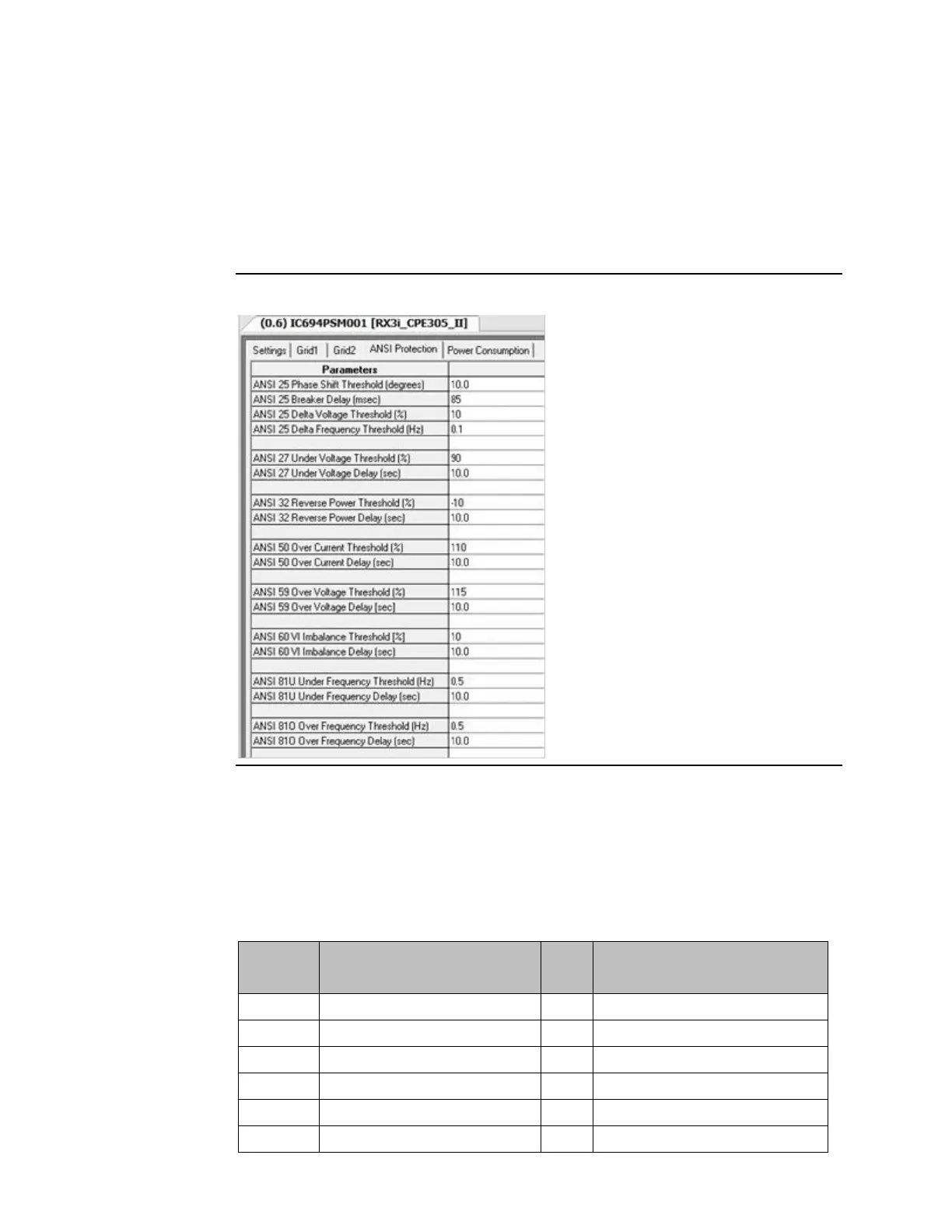
ANSI Protection Tab
Note that synchronization is an option in 3-phase mode, so the ANSI 25 parameters can be
left at their default values or changed to suit the application. In this example, the breaker
delay has been set to 85ms (the total contact closure time from CloseRelayOK signal to
contacts physically closing). This allows the PSM to calculate the precise timing to close the
sync relay as close as possible to 0
⁰
phase angle in a rotating phase angle synchronization.
Figure 30
%Q Configuration Values
This table shows the settings for both grids. These bits must be set during the first PLC scan
when the PLC transitions to run mode. %Q offset 2, 3 & 4 and 18, 19 & 20 set the PSM for the
field voltage and power configuration. Setting these values incorrectly will yield invalid
readings. All remaining bits may be changed during run mode to adapt to changing field
conditions.