12
BOLTED FRAME
THE LIFT CAN BE BOLTED TO LIFT INSTEAD OF WELDED IF REQUIRED.
This is normally done where the lift frame is galvanised, the vehicles rear frame is stainless
steel or the customer specifies.
C/sunk head screws are supplied for this purpose.
With the lift in position, put suitable rags into the column above the runners to prevent swarf
dropping down into the LSD mechanism.
Mark the centres of the exposed mounting holes at the top of the columns on to the rear
frame.
Drill Ø8.5 holes through the rear frame.
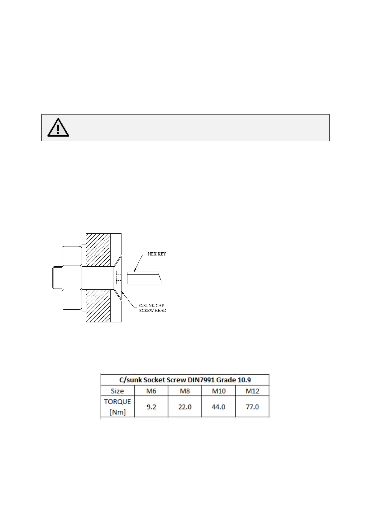
Fit the screws, washers and nylon nuts supplied.
Use a hex key to stop the screw from turning.
Tighten nut with spanner to a torque – see table below.
Remove rags and swarf.
Complete installation of power pack and wiring. Then lower lift platform to expose remaining
mounting holes.
 Loading...