5. System Operation
5
.1 Connections to the User Control Interface (UCI)
Figure 5
UCI power and gas connections on rear of UCI
W
ARNING!
P
ower must be on during all operations including filling
a
nd inflation
Compulsory Connections:
1. Power: 120 V or 230 V (depending on UCI/Motor rating).
Connect to mains supply.
2. Gas supply (air or nitrogen @ 2 – 6 bar regulated) using
10 mm pneumatic air hose
WARNING!
Ensure connections 3 and 4 are open and free to vent
during operation
Optional Connections:
3. BAG VENT 1: Downstream Bag Vent (using optional 12 mm pneumatic hose if collecting
exhaust nitrogen)
4. BAG VENT 2: Upstream Bag Vent (using optional 12 mm pneumatic hose if collecting
exhaust nitrogen)
Optional Connections:
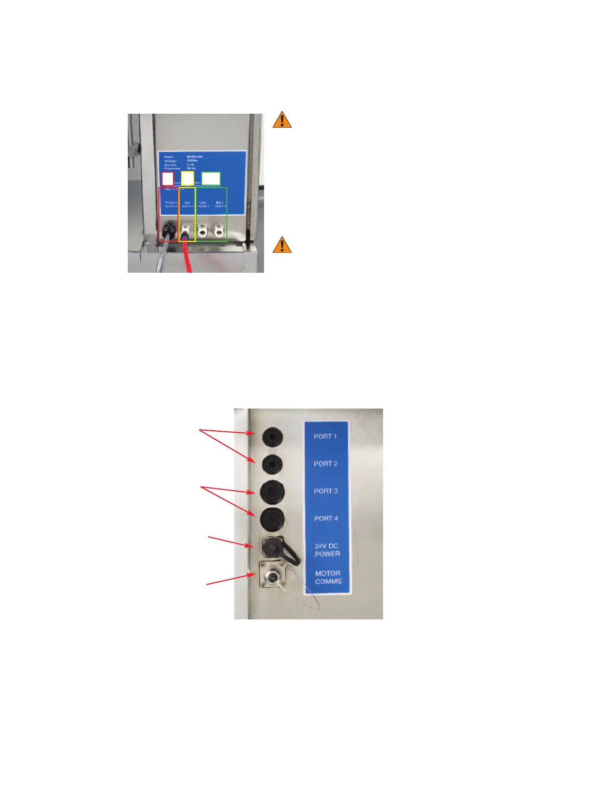
Figure 6
Optional sensor and comms connections UCI INNER FACE FRONT
PORT 1 & PORT 2
Used for connecting appropriate sensor cables at manufacture (depending on mixer configuration).
PORT 3 & PORT 4
Used for connecting appropriate retransmitting cables at manufacture (depending on
mixer configuration).
www.pall.com/biopharm 6
1
2
3, 4
Port 1 & 2
Optional Sensor
Cable Port
Port 3 & 4
Optional Sensor
Signal Retransmit
Ports
MO
TO
R
CO
MMS
Con
n
ection
f
or
A
llegro
MVP System
24 V DC POWER
Power Connection
for Weighing Platform
 Loading...