16
4. Location of Controls and Components
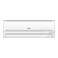
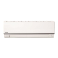
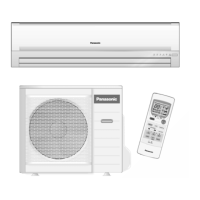
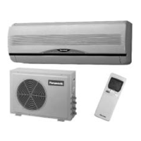
4.1 Indoor Unit
Remote control receiver (Max. 8m)
(Indicator)
(White/Red) (White) (White) (White)
Intake Grille
Dust Sensor
Air Filter B
Indicator Flap
Air Filter A
Horizontal Airflow
Direction Louver
• Do not adjust by hand.
Vertical Airflow
Direction Louver
• Do not adjust by hand.
Auto OFF/ON button
• Use when remote control
nanoe-G Generator
• Do not touch during operation.
is misplaced or a
malfunction occurs.
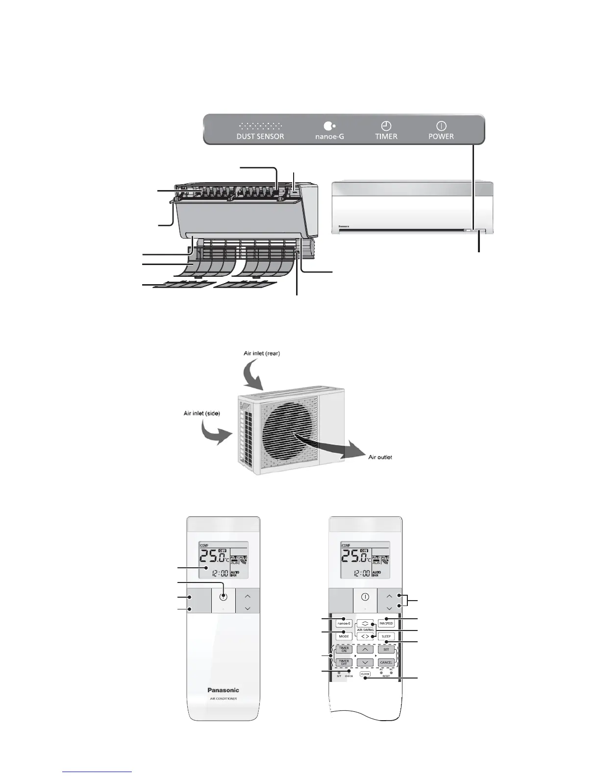
4.2 Outdoor Unit
4.3 Remote Control
iCOMFORT
TEMP
TEMP
SHOWER /
DIRECT
OFF/ON
iCOMFORT
TEMP
TEMP
SHOWER /
DIRECT
OFF/ON
Remote control display
iCOMFORT operation
SHOWER / DIRECT operation
OFF/ON
231
Fan Speed selection
Airflow direction selection
nanoe-G operation
Operation mode
Temperature setting
Timer setting
Check
SLEEP operation
Clock setting
 Loading...