SER NO.
Quick Start Guide STEP 1
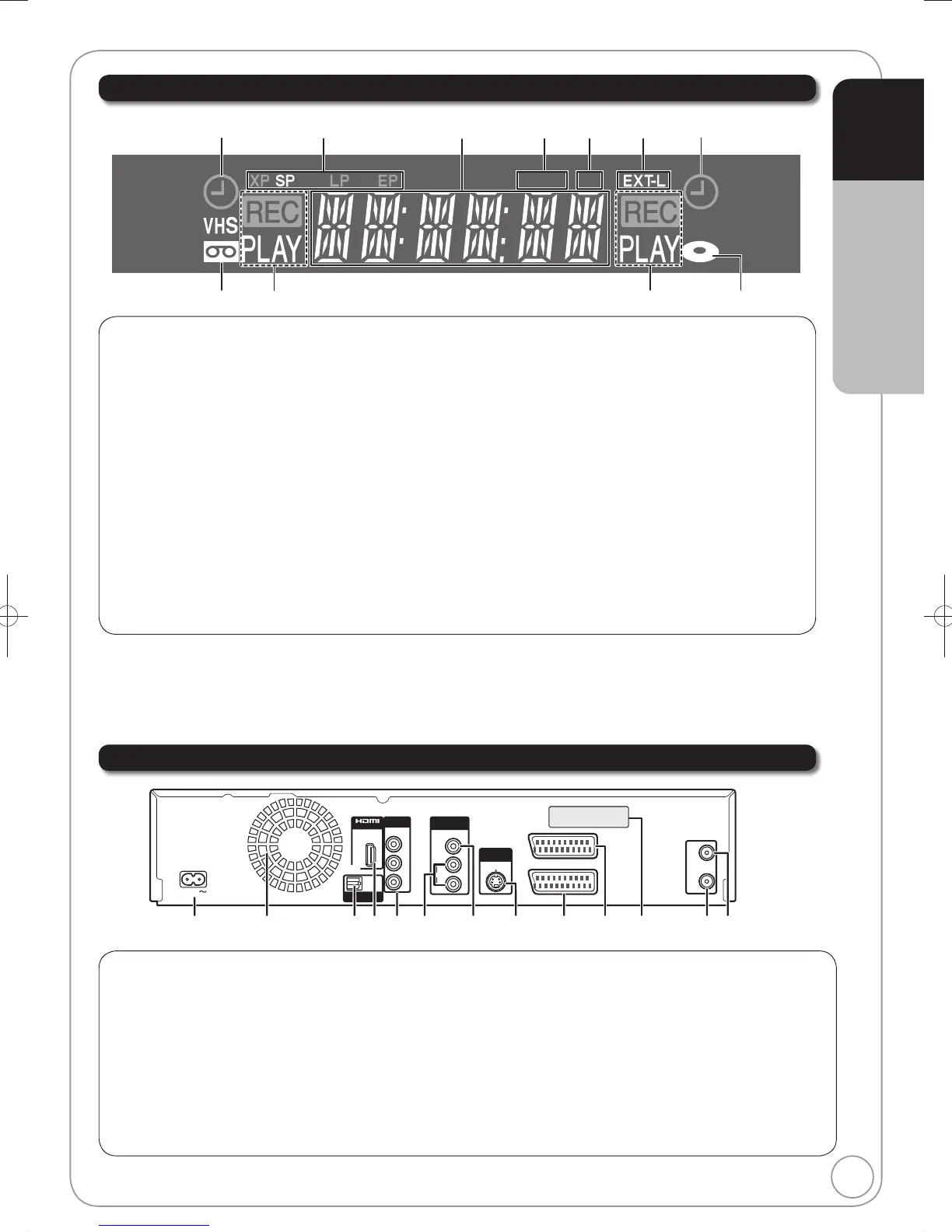
AC IN~ = Power supply
Connection for the AC mains lead
Cooling fan
Digital audio output terminal .......................... (¼ 72)
HDMI AV OUT terminal ..........................(¼ 10, 72)
Digital audio and video output terminal
COMPONENT VIDEO OUT (PROGRESSIVE/
INTERLACE) terminals ................................ (¼ 71)
Y = Luminance signal (brightness), P
B
= Chrominance signal
(colour difference), P
R
= Chrominance signal (colour difference)
AUDIO output terminals.......................... (¼ 71, 72)
Video output terminal ...............................(¼ 71)
S VIDEO output terminal ..........................(¼ 71)
AV2 (EXT) 21-pin Scart terminal ....(¼ 9, 10, 70)
Connection of an external unit
AV1 (TV) 21-pin Scart terminal ..(¼ 8, 9, 10, 70)
TV set connection
Serial number
Aerial output terminal .......................(¼ 8, 9, 70)
Aerial input terminal .........................(¼ 8, 9, 70)
Timer recording indicator (
) ............... (¼ 19)
On:
When a timer recording programme is registered
and a recordable disc or video cassette is
inserted.
Flashes:
When the unit cannot record a timer recording
programme (e.g., there is no disc or video
cassette, etc.).
Tape indicator
Operation status
Recording mode indicator
DVD: ...................................................... (¼ 24)
VHS: ....................................................... (¼ 24)
Main display
Copying indicator
Digital broadcast indicator
Lights when the unit is receiving digital
broadcast or TV Guide data.
Linked timer recordings with external
equipment indicator .............................. (¼ 27)
Disc indicator
For information about the 21-pin Scart terminal (¼ 8)
 Loading...