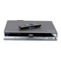
16
RQT8033
Getting started
COMPONENT
VIDEO IN
S VIDEO IN
AUDIO IN
R L
VIDEO IN
Y
P
B
P
R
COMPONENTCOMPONENT
VIDEOVIDEO OUTOUT
(PROGRESSIVE/ (PROGRESSIVE/
INTERLACE)INTERLACE)
OPTICALOPTICAL
DIGITAL AUDIO OUTDIGITAL AUDIO OUT
(PCM/BITSTREAM)(PCM/BITSTREAM)
AV4 IN AV4 IN OUTOUT
AUDIOAUDIO
VIDEOVIDEO
R
L
R
L
S VIDEO OUTS VIDEO OUT
S VIDEOS VIDEO
AV4 INAV4 IN
RF OUT
RF IN
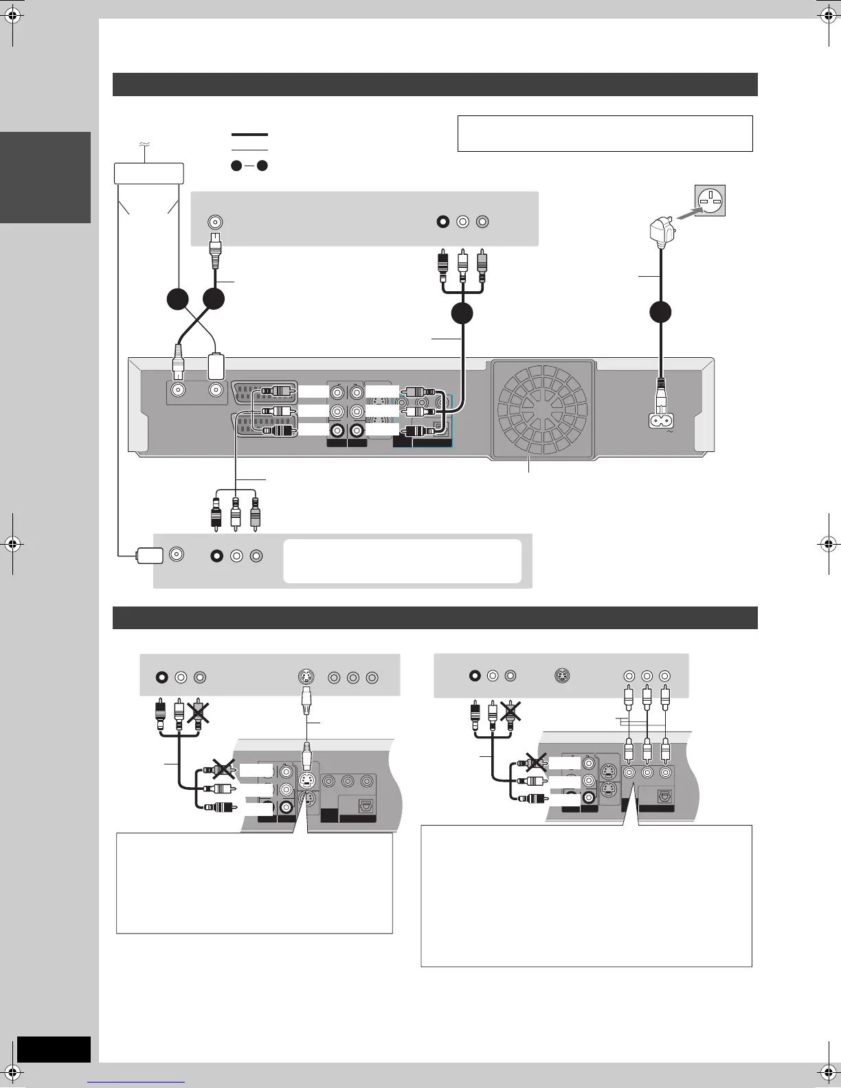
STEP 1
Connection
Connecting to the television using the 21-pin Scart leads (➡ 15)
∫ Component video output
Component signal outputs the colour difference signals (PB/PR) and luminance signal (Y) separately in order to achieve high fidelity in
reproducing colours. If the television is compatible with progressive output, a high quality picture can be output because this unit’s component
video output terminal outputs a progressive output signal (➡ 69).
Connecting a television with AUDIO/VIDEO terminals and VCR
Connecting a television with S VIDEO or COMPONENT VIDEO terminals
R L
AUDIO OUT VIDEO OUT
VHF/UHF
RF IN
1
4
VHF/UHF
RF IN
RF OUT
RF IN
AUDIO IN
R L
VIDEO IN
AC IN
Y
P
B
PR
COMPONENT
VIDEO
OUT
(PROGRESSIVE/
INTERLACE)
OPTICAL
DIGITAL AUDIO OUT
(PCM/BITSTREAM)
S VIDEO OUT
S VIDEO
AV4 IN
AV4 IN
OUT
AUDIO
VIDEO
R
L
R
L
AV1
(
TV
)
AV2
(
EXT
)
3
4
2
1
To the aerial
Splitter
Aerial
lead
Cooling fan
RF coaxial lead
This unit’s rear panel
Audio/Video cable
To household mains socket
(AC 220–240 V, 50 Hz)
You can also connect with the AV2 terminal
on this unit using the 21-pin Scart lead.
Audio/Video cable
Red White Yellow
Red White Yellow
indicates included accessories.
indicates accessories not included.
are required connections. Connect in the numbered order.
Television’s rear panel
VCR’s rear panel
Use a splitter if
you also want to
connect the aerial
to your VCR.
AC mains lead
Connect only after all other
connections are complete.
Red
Yellow
White
Red
Yellow
White
COMPONENT
VIDEO IN
S VIDEO IN
AUDIO IN
R L
VIDEO IN
Y
P
B
PR
COMPONENTCOMPONENT
VIDEOVIDEO OUTOUT
(PROGRESSIVE/ (PROGRESSIVE/
INTERLACE)INTERLACE)
OPTICALOPTICAL
DIGITAL AUDIO OUTDIGITAL AUDIO OUT
(PCM/BITSTREAM)(PCM/BITSTREAM)
AV4 IN AV4 IN OUTOUT
AUDIOAUDIO
VIDEOVIDEO
R
L
R
L
S VIDEO OUTS VIDEO OUT
S VIDEOS VIDEO
AV4 INAV4 IN
RF OUT
RF IN
COMPONENT VIDEO OUT terminal
Connect to COMPONENT VIDEO IN terminal on the television through video
cables. These terminals can be used for either interlace or progressive output
(
➡
69) and provide a purer picture than the S VIDEO OUT terminal.
≥Connect to terminals of the same colour.
≥Video output from the component terminal will have no colour during
EXT LINK recordings. Use a fully wired 21-pin Scart lead between
the TV and the unit when viewing external equipment picture through
the AV2 terminal.
≥Change the “AV1 Output” setting in the SETUP menu (➡ 59) to
“Video (with component)” or “S Video (with component)” after tuning
is completed (➡ 19, 20). If not, the picture will not be in colour.
For progressive output (➡ 22)
Video cable
Audio/Video
cable
Red
White
Yellow
Red White Yellow
Television’s rear panel
Note to owners of progressive compatible PAL system televisions (➡ 6)
Yellow
BE SURE TO READ THE CAUTION FOR THE AC MAINS
LEAD ON PAGE 2 BEFORE CONNECTION.
S VIDEO OUT terminal
Connect to S VIDEO IN terminal on the television
through a S Video cable.
The S VIDEO OUT terminal achieves a more vivid
picture than the VIDEO OUT terminal. (Actual results
depend on the television.)
Audio/
Video
cable
S Video
cable
Red
White
Red White Yellow
Television’s rear panel
EH50.book Page 16 Tuesday, July 5, 2005 11:03 AM
 Loading...