Optical digital output: Optical terminal
Pickup
Wave length: 658 nm / 790 nm
Laser power: CLASS 2a / CLASS 1
NORSK
Pickup
B lgelende: 658 nm / 790 nm
Laser-styrke: lngen farlig str lning sendes ut
KLASSE 2a / KLASS E 1
1 SAFETY PRECAUTIONS
4
1.1. GENERAL GUIDELINES
4
2 PREVENTION OF ELECTRO STATIC DISCHARGE (ESD) TO
ELECTROSTATICALLY SENSITIVE (ES) DEVICES
4
3 Precaution of Laser Diode
5
4 General Description
6
4.1. Operating instructions
6
5 Disassembling the Casing and Checking P.C.B.s
7
5.1. Dissasembly Procedure
7
5.2. Caseing Parts and P.C.B. Positions
7
5.3. Top Cover
8
5.4. Tray
8
5.5. Front Panel
8
5.6. Mechanism Unit
9
5.7. Terminal P.C.B.
9
5.8. Module P.C.B.
9
5.9. Front-1 P.C.B., Front-2 P.C.B., and Front-3 P.C.B.
9
5.10. Rear panel
9
5.11. Scart P.C.B.
10
5.12. Mother P.C.B.
10
5.13. Servicing Position
10
6 PREVENTION OF STATIC ELECTRICITY DISCHARGE
12
6.1. Grounding for electrostatic breakdown prevention
12
6.2. Handling Precautions for Traverse Unit (Optical Pickup)
12
7 OPTICAL PICKUP SELF-DIAGNOSIS AND REPLACEMENT
PROCEDURE
13
7.1. Self-diagnosis
13
7.2. Cautions to Be Used Before Replacing the Optical Pickup
Unit and Spindle Motor Assembly
14
8 SELF-DIAGNOSIS FUNCTION AND SERVICE MODES
15
8.1. Self-diagnosis Function and Service Modes
15
8.2. Service mode table
16
8.3. Servo Process Flow
18
8.4. Servo Process Display Mode
19
8.5. ADSC Internal Ram Data Display
19
8.6. Sales demonstration lock function
20
Power consumption in standby mode:
approx. 4 W
Notes:
Specifications are subject to change without notice.
Mass and dimensions are approximate.
8.7. Service Precautions
20
8.8. Handling After Completing Repairs
20
9 ASSEMBLING AND DISASSEMBLING THE MECHANISM UNIT
21
9.1. Disassembly Procedure
21
9.2. Terminal P.C.B.
21
9.3. Clamp Plate Unit
21
9.4. Tray
22
9.5. Traverse Block
22
9.6. Traverse Gear
22
9.7. Optical Pickup Unit
22
9.8. Disassembling the Middle Chassis
23
9.9. Disassembling the Traverse Gear A
23
9.10. Disassembling the Spindle Motor Unit
23
10 ADJUSTMENT PROCEDURES
24
10.1. Service Tools and Equipment
24
10.2. Important points in adjustment
24
10.3. Storing and Handling Test Discs
24
10.4. Optical adjustment
25
11 Electrical Confirmation
26
11.1. Video Output (Luminance Signal) Confirmation
26
11.2. Video Output (Chrominance Signal) Confirmation
26
12 Abbreviations
27
13 Voltage Chart
29
13.1. Module P.C.B.
29
13.2. Mother P.C.B.
31
13.3. Terminal P.C.B.
32
13.4. Scart P.C.B.
32
14 BLOCK DIAGRAM
33
14.1. OVERALL BLOCK DIAGRAM
33
14.2. SERVO BLOCK DIAGRAM
34
14.3. VIDEO BLOCK DIAGRAM
36
14.4. AUDIO BLOCK DIAGRAM
38
15 SCHEMATIC DIAGRAM
39
15.1. INTERCONNECTION SCHEMATIC DIAGRAM (DVD-
RV31 ONLY)
39
CONTENTS
Page Page
2
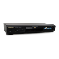
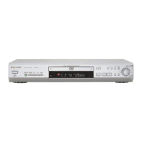
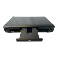
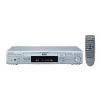
DVD-RV31 / DVD-RV41
 Loading...