Do this confirmation after replacing a P.C.B.
Purpose: To maintain video signal output compatibility.
11 Electrical Confirmation
11.1. Video Output (Luminance Signal) Confirmation
Do this confirmation after replacing a P.C.B.
Measurement point Mode Disc
Video output terminal Color bar 75%
PLAY (Title 46):DVDT-S15
PLAY (Title 12):DVDT-S01
DVDT-S15
or
DVDT-S01
Measuring equipment, tools Confirmation value
Screwdriver, Oscilloscope
200mV/div, 10µsec/div
1000mVp-p±30mV
Purpose: To maintain video signal output compatibility.
1. Connect the oscilloscope to the video output terminal and terminate at 75 ohms.
2. Confirm that the luminance signal (Y+S) level is 1000 mVp-p±30 mV.
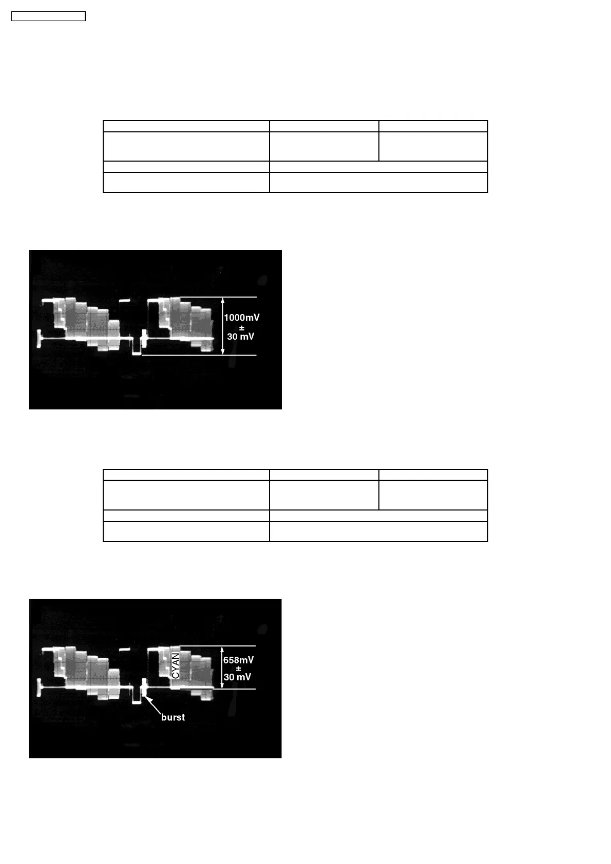
11.2. Video Output (Chrominance Signal) Confirmation
Measurement point Mode Disc
Video output terminal Color bar 75%
PLAY (Title 46):DVDT-S15
PLAY (Title 12):DVDT-S01
DVDT-S15
or
DVDT-S01
Measuring equipment, tools Confirmation value
Screwdriver,Oscilloscope
200mV/div, 10µsec/div
658mVp-p±30mV
1. Connect the oscilloscope to the video output terminal and terminate at 75 ohms.
2. Confirm that the chrominance signal (C) level is 658 mVp-p±30 mV.
26
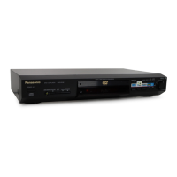
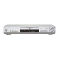
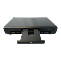
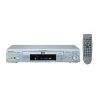
DVD-RV31 / DVD-RV41
 Loading...