Do you have a question about the Panasonic DVD-RV31 and is the answer not in the manual?
| Brand | Panasonic |
|---|---|
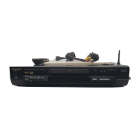
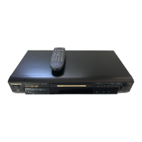
| Model | DVD-RV31 |
| Category | DVD Player |
| Language | English |
General guidelines for servicing the equipment safely.
Procedure to check leakage current with the unit unplugged.
Procedure to check leakage current with the unit powered on.
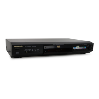
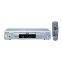
Describes operating instructions for the main unit and remote control.
Step-by-step procedure for disassembling the unit's casing.
Diagram showing the location of casing parts and PCBs.
Instructions for removing the top cover of the unit.
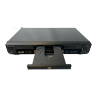
Procedure for removing and disassembling the disc tray mechanism.
Steps for removing the front panel assembly.
Procedure for removing the entire mechanism unit.
Steps for removing the terminal printed circuit board.
Instructions for removing the module printed circuit board.
Procedure for removing front panel PCBs.
Steps for removing the rear panel.
Instructions for removing the SCART printed circuit board.
Procedure for removing the mother printed circuit board.
Description of servicing positions for internal components.
Shows the servicing position for the terminal PCB.
Methods for grounding to prevent electrostatic breakdown.
Procedure for grounding the worktable.
Method for grounding the human body using an anti-static strap.
Specific precautions for handling the optical pickup unit.
Procedure for performing self-diagnosis of the optical pickup.
Important cautions and procedures before replacing optical pickup and spindle motor.
Overview of self-diagnosis features and service modes.
Table detailing service modes, button combinations, and functions.
Diagram illustrating the servo process flow during operation.
Explanation of the servo process display numbers and their meanings.
Details on displaying servo learning values from ADSC internal RAM.
Feature to disable disc eject for sales demonstrations.
Important service precautions and procedures.
Procedure for recovery after replacing FROM or EEPROM.
Information on updating the player's firmware.
Steps and precautions after completing unit repairs.
Method for handling the unit after repairs are completed.
Precautions to follow after completing unit repairs.
Step-by-step procedure for disassembling the mechanism unit.
Procedure for removing the terminal PCB from the mechanism.
Steps for removing the clamp plate unit.
Procedure for removing the tray.
Steps for removing the traverse block from the chassis.
Procedure for disengaging and removing traverse gears.
Steps for removing the optical pickup unit.
Procedure for disassembling the middle chassis.
Steps for removing the traverse gear A.
Procedure for disassembling the spindle motor unit.
List of service tools and equipment required for adjustments.
Key considerations before performing adjustments.
Specific points regarding optical adjustment procedures.
Key points for electrical adjustment procedures.
Guidelines for storing and handling test discs.
Procedures for optical adjustments.
Procedure for adjusting the optical pickup tilt.
Confirming the luminance signal level of the video output.
Confirming the chrominance signal level of the video output.
Voltage chart for the module PCB.
Voltage chart for the mother PCB.
Voltage chart for the terminal PCB.
Voltage chart for the SCART PCB.
Overall system block diagram of the DVD player.
Block diagram detailing the servo control system.
Block diagram illustrating the video signal path and processing.
Block diagram showing the audio signal path and processing.
Interconnection schematic for DVD-RV31 model.
Interconnection schematic for DVD-RV41 model.
Schematic diagram of the power supply section on the mother PCB.
Schematic diagram of the video output section on the mother PCB.
Schematic diagram of the Audio Out 1 section on the mother PCB.
Schematic diagram of the Audio Out 2 section on the mother PCB.
Schematic diagram of the operation section on the mother PCB.
Schematic diagram of the ADSC section on the module PCB.
Schematic diagram of the ODC section on the module PCB.
Schematic diagram of the AV Decoder section on the module PCB.
Schematic diagram of the Video D/A Converter section on the module PCB.
Schematic diagram of the Audio D/A Converter section on the module PCB.
Schematic diagram of the CPU section on the module PCB.
Schematic diagram of the terminal connections.
Schematic diagram for the SCART connector and related circuitry.
Schematic diagrams for the front panels of the DVD-RV31.
Schematic diagrams for the front panels of the DVD-RV41.
Layout of the components on the Mother PCB.
Address mapping information for Mother and Module PCBs.
Component layout for the Module PCB (Part 1).
Component layout for the Module PCB (Part 1, Foil side).
Layout of components on the Terminal PCB.
Component layout for the SCART PCB.
Component layouts for Front 1 and Front 2 PCBs (DVD-RV31).
Component layouts for Front 1 and Front 2 PCBs (DVD-RV41).
Exploded view of casing and mechanism parts for DVD-RV31.
Exploded view of casing and mechanism parts for DVD-RV41.
Detailed exploded view of the mechanism section.
Exploded view of packing materials and accessories.
Information about the replacement edition of the manual.
Precautions to take when replacing the optical pickup unit.
Guidance on using optical pickups for various models.
Policy for repairing or replacing the DL1 mechanism's optical pickup.
Detailed steps for replacing the optical pickup unit.
Details on changes to replacement parts lists and exploded views.
Updates to the replacement parts list for specific models.
Updates to the replacement parts list for specific models.
Updates to the replacement parts list for specific models.
Notification of changes to the replacement parts list.
Specific changes to the replacement parts list.
Specific changes to the replacement parts list.
Specific changes to the replacement parts list.
Specific changes to the replacement parts list.
Specific changes to the replacement parts list.
Specific changes to the replacement parts list.