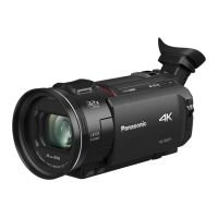
26
8.3. Disassembly Procedure for the
Unit
No. Item Fig Removal
1 Side Case-L Unit (Fig. D1) Screw (A) x 3
(Fig. D2) Screw (B) x 1
Locking tab x 3
Hooking part x 3
Side Case-L Unit
2 Top Case Unit,
Power Panel Light,
LED Piece,
Jack Cover Piece,
Jack Cover Spring,
SS Button, SS Lever,
Jack Cover Unit
(Fig. D3) Screw (C) x 1
Locking tab x 3
Top Case Unit
Power Panel Light
LED Piece
Screw (D) x 1
Convex x 1
Hooking part x 1
Jack Cover Piece
Jack Cover Spring
SS Button
SS Lever
Jack Cover Unit
3 Front Case Unit (Fig. D4) Screw (E) x 1
Screw (F) x 2
FP6003 (Flex)
Screw (G) x 1
Convex x 2
(Fig. D5) Front Case Unit
4NFC P.C.B. Unit
(HC-V270 only)
(Fig. D6) Screw (H) x 1
FP6006 (Flex)
Hooking part x 1
NFC P.C.B. Unit
5Wi-Fi P.C.B.
(HC-V270 only)
(Fig. D7) Flex A
Screw (I) x 1
Wi-Fi P.C.B.
Hooking part x 2
Heat Radiation Plate-L Unit
6 Lens Frame Unit (Fig. D8) Screw (J) x 1
Screw (K) x 1
P6003 (Connector)
Screw (L) x 1
Convex x 2
Locking tab x 2
(Fig. D9) Lens Frame Unit
7 Camera Lens Unit (Fig. D10) FP301 (Flex)
FP6008 (Flex)
Convex x 2
Camera Lens Unit
8Main P.C.B.,
SD Holder P.C.B.
(Fig. D11) Screw (M) x 1
Screw (N) x 3
Screw (O) x 1
Convex x 2
Hooking part x 1
Heat Radiation Plate Unit
P6401 (Connector)
FP6001 (Flex)
FP6402 (Flex)
(Fig. D12) Convex x 5
Locking tab x 4
Bottom Frame Unit
Main P.C.B.
SD Holder P.C.B.
9 Top Operation,
BATT. Catcher P.C.B.
(Fig. D13) Convex x 1
Hooking part x 1
Locking tab x 1
Top Operation
Hooking part x 1
BATT. Catcher P.C.B.
10 R Frame Unit,
Speaker,
LCD Unit
(Fig. D14) Screw (P) x 2
Locking tab x 4
R Frame Unit
Convex x 1
LCD Lever
(Fig. D15) Convex x 2
Convex x 6
Speaker
Convex x 2
LCD Unit
11 Monitor P.C.B.,
LCD Hinge Unit,
Light Guide Plate Unit,
LCD Panel Unit
(Fig. D16) Screw (Q) x 2
Locking tab x 9
LCD Case (T) Unit
Screw (R) x 1
FP901 (Flex)
FP904 (Flex)
FP905 (Flex)
(Fig. D17) Locking tab x 1
Hooking part x 1
Monitor P.C.B.
LCD Hinge Unit
LCD Frame A
Locking tab x 4
Light Guide Plate Unit
LCD Panel Unit
(Fig. D18) Reflection Sheet
Light Guide Plate
Diffusion Sheet
Prism Sheet (B)
Prism Sheet (A)
LGP Holder
12 Spring Holder,
Barrier Lever
(Fig. D19) Screw (S) x 1
Spring Holder
Barrier Spring
Locking tab x 2
Barrier Lever
13 Front Base,
Barrier R,
Barrier F
(Fig. D20) Projection part x 3
Lens Damper Rubber
Screw (T) x 4
Convex x 3
Front Base
Barrier R
Barrier F
14 Front Case,
Mic Cover,
Front Ornament Ring,
Flare Cut Piece,
Microphone Unit
(Fig. D21) Screw (U) x 2
Locking tab x 1
Front Case
Mic Cover
Front Ornament Ring
Flare Cut Piece
Mic Sponge-F
Mic Sponge-M
Microphone Unit
Mic Sponge-R
15 MOS Unit,
IR Cut Grass
(Fig. D22) Screw (V) x 3
MOS Unit
MOS Cushion
IR Cut Grass
(Fig. D23) NOTE: (When Installing
the MOS Unit)
(Fig. D24)
No. Item Fig Removal

 Loading...