EasyManua.ls Logo

Panasonic HC-V270PP User Manual

Panasonic HC-V270PP
63 pages
To Next Page IconTo Next Page
Page #1 background imageLoading...
Page #1 background image
© Panasonic Corporation 2015 Unauthorized copy-
ing and distribution is a violation of law.
ORDER NO.VM1501005CE
B27
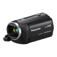
High Definition Video Camera
Model No. HC-V270PP
HC-V270PU
HC-V270EB
HC-V270EC
HC-V270EE
HC-V270EF
HC-V270EG
HC-V270EP
HC-V270GC
HC-V270GK
HC-V270GN
HC-V270GW
HC-V260EE
Colour
(K)...........Black Type
(R)...........Red Type (only HC-V270EG/EP/GC/GK)
(W)...........White Type (only HC-V270GC/V260EE)

Table of Contents

Question and Answer IconNeed help?

Do you have a question about the Panasonic HC-V270PP and is the answer not in the manual?

Panasonic HC-V270PP Specifications

General IconGeneral
BrandPanasonic
ModelHC-V270PP
CategoryCamcorder
LanguageEnglish

Summary

1 Safety Precautions

1.1 General Guidelines

Essential safety precautions for servicing, including component replacement and electrical shock prevention.

2 Warnings and Battery Recycling

2.1 Electrostatic Discharge (ESD) Prevention

Techniques to prevent component damage from static electricity during handling and servicing.

2.4 Lithium Battery Replacement

2.4.1 Replacement Procedure

Step-by-step guide to remove and replace the lithium battery, including CAUTION.

3.5 PCB and IC Baking Procedure

6 Service Mode Overview

Service Mode Menu Functions

Overview of the service mode menu options for diagnostics and adjustments.

6.1 Model/Destination Settings

6.2 Lock Search and Error History Indication

6.3 Power ON Self Check Result Display

6.4 Service Adjustment Function

6.5 Restore Backed Up Adjustment Data

6.6 Touch Panel Calibration

6.7 NFC Initialization (HC-V270 only)

8 Disassembly and Assembly Instructions

8.1 Disassembly Flow Chart

Provides a visual flowchart for the unit's disassembly and assembly process.

8.2 PCB Location

8.3 Detailed Disassembly Procedures

8.3.8 Main P.C.B. and SD Holder P.C.B. Removal

Instructions for removing the main PCB and SD holder PCB.

8.3.11 Monitor P.C.B. and LCD Unit Removal

Instructions for removing monitor PCB, LCD hinge, light guide plate, and LCD panel.

9 Measurements and Adjustments

9.1 Electric Adjustment Procedure

Details the electric adjustment process using specific jigs and connection methods.

9.1.2 Adjustment Items Overview

9.1.3 Adjustment Procedure Execution

9.1.3.1 Model Setting for Adjustment

Detailed steps for setting the model/destination, especially after PCB replacement.

9.1.3.5 Camera Adjustment Entry

Entry point for performing camera-specific adjustments.

9.1.3.7 Indoor White Balance Adjustment

Procedure for indoor white balance adjustment using specific setup conditions.

9.1.3.8 Outdoor White Balance Adjustment

Procedure for outdoor white balance adjustment using specific setup conditions.

10 Factory Setting Procedure

10.1 Activating Factory Settings

Steps to activate the factory settings mode for the unit.

11.2 Camera/System Control Circuit Diagram

11.3 Video/Audio Signal Process Circuit Diagram

11.4 Video/Audio Signal Process(2) Circuit Diagram

11.5 Lens Drive Circuit Diagram

11.6 Power Supply Circuit Diagram

Related product manuals