Items Check
Point
Procedure Check or
Replace Parts
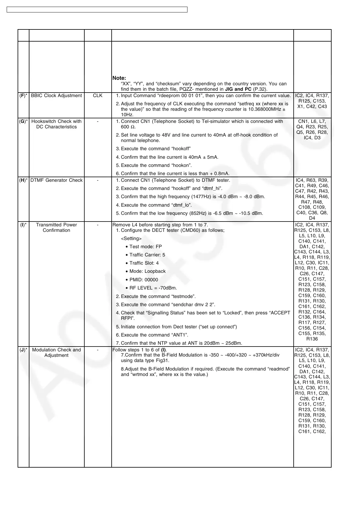
(E)* EEP-ROM Confirmation - 1. EEP-ROM Confirmation (Execute the command “ChkTCD240XXrevYY”).
XX: country code
YY: revision number
2. Confirm the returned checksum value.
Note:
“XX”, “YY”, and “checksum” vary depending on the country version. You can
find them in the batch file, PQZZ- mentioned in JIG and PC (P.32).
IC3, C53, R56,
R57, C57, Q6,
Q7, R64, R65,
R35
(F)* BBIC Clock Adjustment CLK 1. Input Command “rdeeprom 00 01 01”, then you can confirm the current value.
2. Adjust the frequency of CLK executing the command “setfreq xx (where xx is
the value)” so that the reading of the frequency counter is 10.368000MHz ±
10Hz.
IC2, IC4, R137,
R125, C153,
X1, C42, C43
(G)* Hookswitch Check with
DC Characteristics
- 1. Connect CN1 (Telephone Socket) to Tel-simulator which is connected with
600 Ω.
2. Set line voltage to 48V and line current to 40mA at off-hook condition of
normal telephone.
3. Execute the command “hookoff”
4. Confirm that the line current is 40mA ± 5mA.
5. Execute the command “hookon”.
6. Confirm that the line current is less than + 0.8mA.
CN1, L6, L7,
Q4, R23, R25,
Q5, R26, R28,
IC4, D3
(H)* DTMF Generator Check - 1. Connect CN1 (Telephone Socket) to DTMF tester.
2. Execute the command “hookoff” and “dtmf_hi”.
3. Confirm that the high frequency (1477Hz) is -4.0 dBm ~ -8.0 dBm.
4. Execute the command “dtmf_lo”.
5. Confirm that the low frequency (852Hz) is -6.5 dBm ~ -10.5 dBm.
IC4, R63, R39,
C41, R49, C46,
C47, R42, R43,
R44, R45, R46,
R47, R48,
C108, C109,
C40, C36, Q8,
D4
(I)* Transmitted Power
Confirmation
- Remove L4 before starting step from 1 to 7.
1. Configure the DECT tester (CMD60) as follows;
<Setting>
• Test mode: FP
• Traffic Carrier: 5
• Traffic Slot: 4
• Mode: Loopback
• PMID: 00000
• RF LEVEL = -70dBm.
2. Execute the command “testmode”.
3. Execute the command “sendchar dmv 2 2”.
4. Check that “Signalling Status” has been set to “Locked”, then press “ACCEPT
RFPI”.
5. Initiate connection from Dect tester (“set up connect”)
6. Execute the command “ANT1”.
7. Confirm that the NTP value at ANT is 20dBm ~ 25dBm.
IC2, IC4, R137,
R125, C153, L8,
L5, L10, L9,
C140, C141,
DA1, C142,
C143, C144, L3,
L4, R118, R119,
L12, C30, IC11,
R10, R11, C28,
C26, C147,
C151, C157,
R123, C158,
R128, R129,
C159, C160,
R131, R130,
C161, C162,
R132, C164,
C136, R134,
R117, R127,
C156, C154,
C155, R135,
R136
(J)* Modulation Check and
Adjustment
- Follow steps 1 to 6 of (I).
7.Confirm that the B-Field Modulation is -350 ~ -400/+320 ~ +370kHz/div
using data type Fig31.
8.Adjust the B-Field Modulation if required. (Execute the command “readmod”
and “wrtmod xx”, where xx is the value.)
IC2, IC4, R137,
R125, C153, L8,
L5, L10, L9,
C140, C141,
DA1, C142,
C143, C144, L3,
L4, R118, R119,
L12, C30, IC11,
R10, R11, C28,
C26, C147,
C151, C157,
R123, C158,
R128, R129,
C159, C160,
R131, R130,
C161, C162,
R132, C164,
C136, R134,
R117, R127,
C156, C154,
C155, R135,
R136
28
KX-TG1233BXS / KX-TG1233BXT / KX-TCA122CXS / KX-TCA122CXT / KX-TCA121CXS / KX-TCA121CXT
 Loading...