6 <SHUTTER> button
Used to turn off the audio and video temporarily. (x page 54)
7 <AUTO SETUP> button
Used to automatically adjust with auto setup function while
projecting the image (x page 55). It is also used to operate the
Memory Viewer screen.
8 asqw buttons
Used to select the menu screen items, switch the setting or
adjust the level.
Also used to enter a password in the [SECURITY] menu or enter
characters.
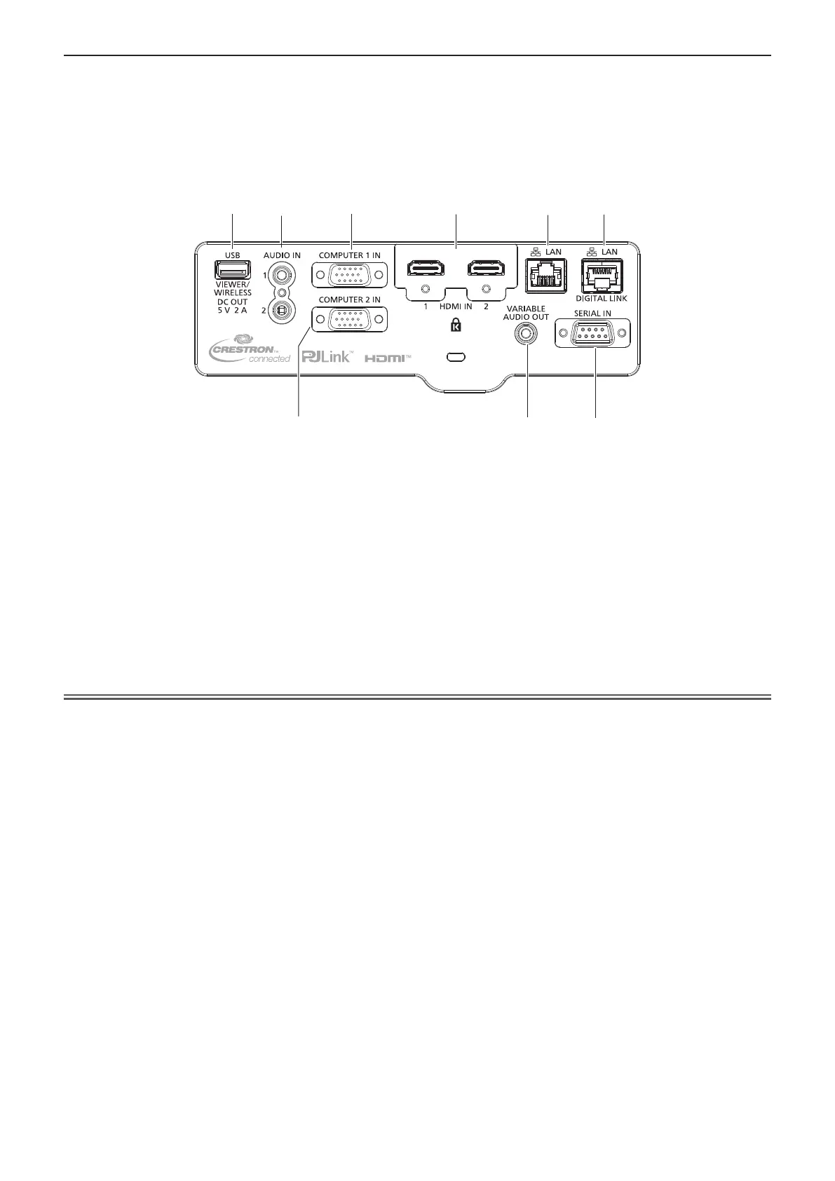
r Connecting terminals
1
5
6
2
3
7
4
8
9
1 <USB (VIEWER/WIRELESS/DC OUT)> terminal
When using the Memory Viewer function, attach the USB
memory directly to this terminal. (x page 112)
Attach the wireless module (Model No.: AJ-WM50) directly to this
terminal when using the wireless LAN function. (x page 117)
In addition, this terminal can be used for power supply (DC 5 V,
maximum 2 A).
2 <AUDIO IN 1> terminal / <AUDIO IN 2> terminal
These are the terminals to input audio signals.
3 <COMPUTER 1 IN> terminal
This is the terminal to input RGB signals or YC
B
C
R
/YP
B
P
R
signals.
4 <COMPUTER 2 IN> terminal
This is the terminal to input RGB signals or YC
B
C
R
/YP
B
P
R
signals.
5 <HDMI IN 1> terminal / <HDMI IN 2> terminal
These are the terminals to input HDMI signal.
6 <LAN> terminal
This is the LAN terminal to connect to the network.
This also supports the image transfer from the image transfer
application software.(x page 115)
7 <DIGITAL LINK/LAN> terminal
(Not available for PT-VMZ51S and PT-VMZ41)
This is a terminal to connect a device that transfer image signal
or audio signal. Also, this is the LAN terminal to connect to the
network.
8 <VARIABLE AUDIO OUT> terminal
This is the terminal to output the input audio signal.
9 <SERIAL IN> terminal
This is the RS-232C compatible terminal to externally control the
projector by connecting a computer.
Attention
f When the [PROJECTOR SETUP] menu → [ECO MANAGEMENT] → [STANDBY MODE] is set to [NORMAL], the <USB (VIEWER/
WIRELESS/DC OUT)> terminal can supply power even in standby state. If set to [ECO], the <USB (VIEWER/WIRELESS/DC OUT)>
terminal can not supply power in standby state.
f When an external device exceeding the rating (DC 5 V, maximum 2 A) is connected to the <USB (VIEWER/WIRELESS/DC OUT)> terminal,
an error is detected and the power supply will be stopped. At this time, disconnect the external device, cut off the power of the projector and
then reconnect the power plug to the outlet.
f When a LAN cable is directly connected to the projector, the network connection must be made indoors.
The signal may deteriorate due to the effect of noise or cable length.
f To transmit the Ethernet and serial control signals using the <DIGITAL LINK/LAN> terminal, set the [NETWORK] menu → [ETHERNET
TYPE] to [DIGITAL LINK] or [LAN & DIGITAL LINK].
f To transmit the Ethernet signal using the <LAN> terminal, set the [NETWORK] menu → [ETHERNET TYPE] to [LAN] or [LAN & DIGITAL
LINK].
f The <DIGITAL LINK/LAN> terminal and the <LAN> terminal are connected inside of the projector when the [NETWORK] menu →
[ETHERNET TYPE] is set to [LAN & DIGITAL LINK]. Do not directly connect the <DIGITAL LINK/LAN> terminal and the <LAN> terminal
using a LAN cable. Construct the system so that it is not connected to the same network via the peripherals such as the switching hub or the
twisted-paircable transmitter.
28 - ENGLISH
Chapter 1 Preparation - About your projector

 Loading...