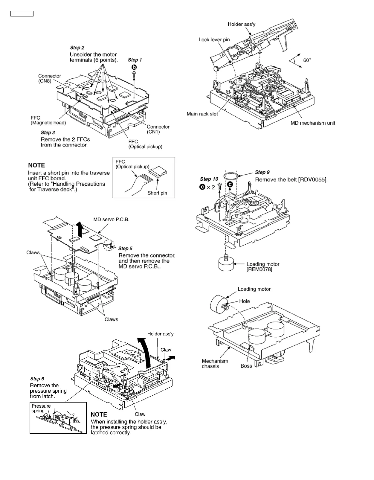
8.3.4. Replacement for the Belt and
Loading Motor Assembly
Step 4
Release the 4 claws.
Step 7
Release the 2 claws and then lift up the holder ass’y.
Note
: When installing the holder ass’y, align the lock lever pin
with the main rack slot.
Step 8
Set the holder ass’y and MD mechanism unit at a 60
degree angle, and then pull out the holder ass’y.
Notice for installing the loading motor
• Align the hole of loading motor with the boss of mechanism
chassis and then install the loading motor.
8.3.5. Replacement for the Traverse
Motor Assembly
• Follow
Step 1
~
Step 8
of item 1.3.4 in Main Component
Replacement Procedures.
18
SA-PM30MD