(All schematic diagrams may be modified at any time with
the development of new technology)
Note :
S1 PROTECT detect switch
S2 REFLECT detect switch
S3 LOAD OPEN detect switch
S4 DISC IN detect switch
S5 LOAD PLAY/REC detect switch
S6 LOAD PLAY detect switch
S7 LOAD TRG detect switch
S8 Traverse detect switch
S701 Reset switch
S971 Mode detect switch
S972 Tape detect switch
S973 CrO2 detect switch
S974 Record detect switch
S975 Record detect switch
SW751 Tape open switch
SW752 Memory/Enter switch
SW753 MD edit switch
SW754 CANCEL switch
SW755 MD REC MODE select switch
SW756 MD & TAPE REC select switch
SW757 TAPE REC/PAUSE switch
SW758 MD REC/PAUSE switch
SW759 CD EDIT switch
SW760 AUX select switch
SW761 P-MD select switch
SW763 GLIDE OPEN/CLOSE switch
SW764 CLOCK/TIMER switch
SW765 PLAY/REC TIMER switch
SW766 TUNE/TIME ADJ UP/+ switch
SW767 TUNE/TIME ADJ DOWN/- switch
SW775 POWER switch
SW776 ECO MODE select switch
SW777 TUNER/BAND select switch
SW778 TAPE select, forward/reverse play switch
SW779 MD select, play/pause switch
SW780 CD select, play/pause switch
SW781 Reverse/Skip switch
SW782 Forward/Skip switch
SW783 Stop switch
SW784 CD OPEN/CLOSE switch
SW785 MD EJECT switch
SW800 System reset switch
VR1 Laser power adjust VR
VR751 Volume control VR
VR752 Treble control
VR753 Bass control VR
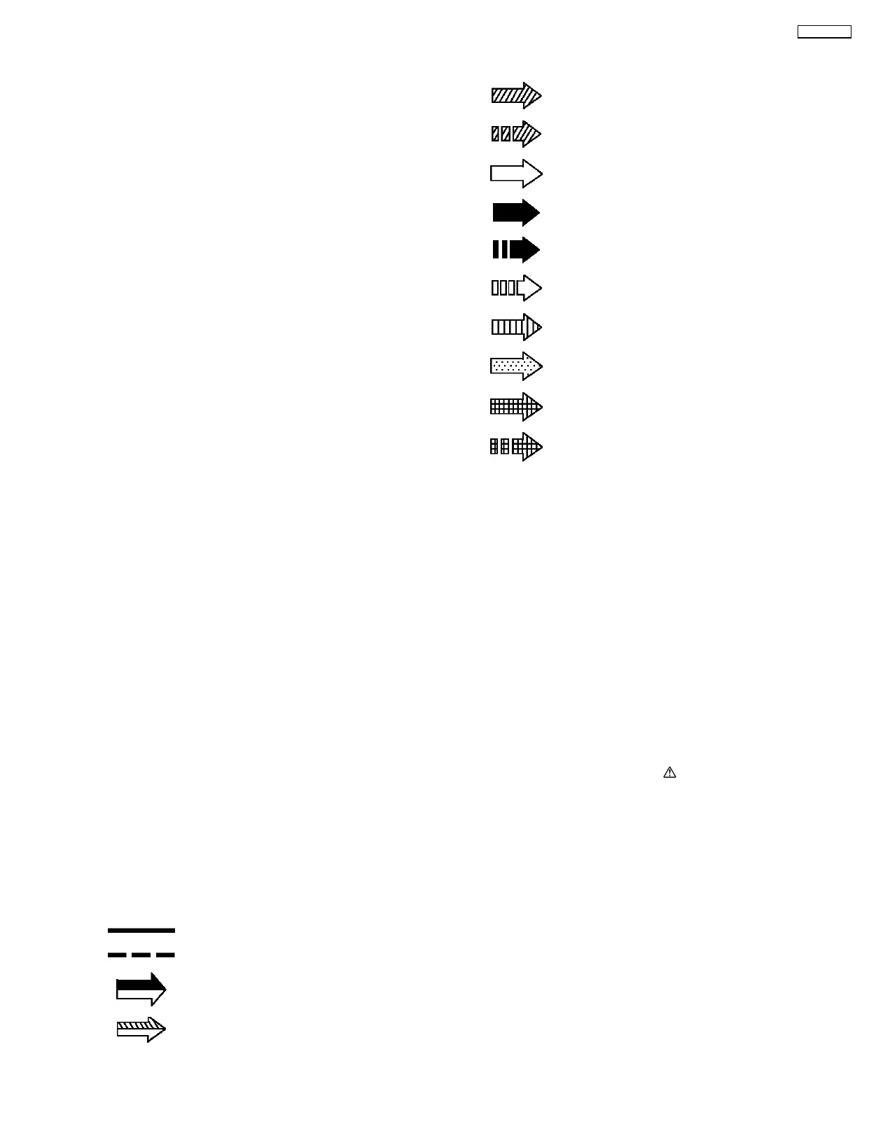
Signal line
: +B line
: -B line
: FM/AM signal line
: Main signal line
: Playback signal line
: Record signal line
: FM signal line
: AM signal line
: AM OSC signal line
: FM OSC signal line
: AUX signal line
: CD signal line
: MD signal line
: MD record signal line
• The voltage value and waveforms are the reference voltage
of this unit measured by DC electronic voltmeter (high
impedance) and oscilloscope on the basis of chassis.
Accordingly, there may arise some error in voltage values
and waveforms depending upon the internal impedance of
the tester or the measuring unit.
No mark : Playback
<< >> : Rec
(( )) : CD
<> :FM
() :AM
(for MD Servo
Circuit)
( ) : MD play [1kHz, L+R, 0dB]
< > : MD rec. [1kHz, L+R, 0dB]
{} :MD
• Importance safety notice :
Components identified by
mark have special
characteristics important for safety. Furthermore, special
parts which have purposes of fire-retardant (resistors), high-
quality sound (capacitors), low-noise (resistors), etc. are
used. When replacing any of components, be sure to use
only manufacturer´s specified parts shown in the parts list.
Caution !
IC, LSI and VLSI are sensitive to static electricity.
Secondary trouble can be prevented by taking care during
repair.
• Cover the parts boxes made of plastics with aluminium foil.
• Put a conductive mat on the work table.
• Ground the soldering iron.
• Do not touch the pins of IC, LSI or VLSI with fingers directly.
14 Schematic Diagram
43
SA-PM30MD