45
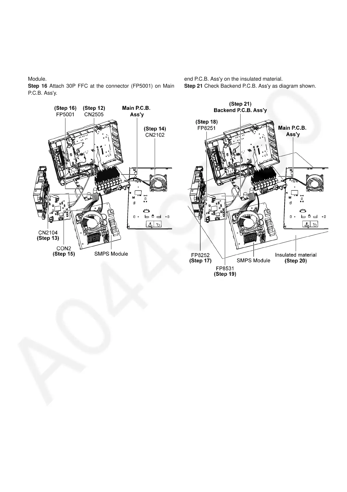
Step 12 Attach 5P Cable at the connector (CN2505) on Main
P.C.B. Ass'y.
Step 13 Attach 2P Wire at the connector (CN2104) on Main
P.C.B. Ass'y.
Step 14 Attach 2P Wire at the connector (CN2102) on Main
P.C.B. Ass'y.
Step 15 Attach 13P Cable at the connector (CON2) on SMPS
Module.
Step 16 Attach 30P FFC at the connector (FP5001) on Main
P.C.B. Ass'y.
Step 17 Attach 5P FFC at the connector (FP8252) on Backend
P.C.B. Ass'y.
Step 18 Attach 6P FFC at the connector (FP8251) on Backend
P.C.B. Ass'y.
Step 19 Attach 24P FFC at the connector (FP8531) on Back-
end P.C.B. Ass'y.
Step 20 Place the Main P.C.B. Ass'y, SMPS Module and Back-
end P.C.B. Ass'y on the insulated material.
Step 21 Check Backend P.C.B. Ass'y as diagram shown.