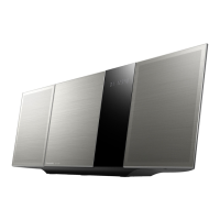
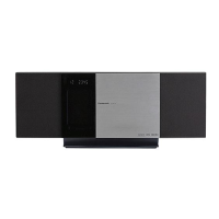
Main set power ON
Power do not turn on
Power on by remote control
OK
Check the connection of FFC connector from FL PCB to Main PCB
Check the 14P of [FL]-[Main] FFC connector CN900 to CN6007. (For HC395/HC397)
Check the 12P of [Panel]-[Main] FFC connector CN6801 to CN8001. (For HC195/HC295/HC297)
(The FL display "HELLO" do not show up)
FFC wire checking
Check the 14P of [FL]-[Main] FFC. (For HC395/HC397)
Switch button operation checking
Power buttons is KEY1 line → 1.5V, if press will momentary drop to 0.198V~0.489V range
Power on by remote control
NG Check the connection of FFC connector from FL PCB to Main PCB
Check [FL] CN900(14Pin) → 1.5V, CN900(12Pin) → 3.3V (For HC395/HC397)
Check [FL] CN6801(4Pin) → 1.5V, CN8001(2Pin) → 3.3V (For HC195/HC295/HC297)Check the B-B connector from SMPS PCB to Main PCB
[Switching power module] P1700(5,7Pin) →8.5V to 19V ; P1700 (2Pin) → 0V to 3.3V
Checking the system +3.3V circuit
Check [Main] IC1108(3Pin) → 3.3V (For HC395/HC397)
Check [Main] IC1102(3Pin) → 3.3V (For HC195/HC295/HC297)
Checking the AC inlet jack
Check [Switching power module]-[ACinlet] wire, copper pattern and solder condition.
Checking fuse OPEN/blow
Check the continuity of [Switching power module] F1 FUSE.
Power ON but turn off immediately Error contents
ޓ
F76 Check all for output SPEAKER shorted or presence of DC voltage Check the IC400 overcurrent, overheating, failure of [DSP] → [DSP] exchange.
ޓޓ
Error contents
ޓ
F61 Check all LDO, DC-DC output supply ICs/devices Check the each power supply for short or OVP (eg AMP Vcc ,+12V,+5.6, +5.28V,+3.3,+1.8V)
Power ON but FL display ERROR
Error contents
ޓ
F70
Check BT signal continuity to SoC/MCU
[Main] BT & communication error of the microcomputer/SoC → [Main] board exchange or [BT] module exchange.
Error contents
ޓ
F77
Check BT MAC address if loaded or not NO BT MAC address downloaded thus cannot recognize by SoC, failure of IC8001 or IC8004.
Plug in AC cord FL display "SMPS NG" Error contents
ޓ
SMPS NG
1) Check resistors region code setting of SMPS P.C.B and
Main P.C.B mode code if matching. Refer to Table A :
Replace SMPS P.C.B, It is wrong region
Replace IC1106 if abnormal voltage
Replace IC8001 (1.55V abnormal or L1108)
Fuse OPEN/Blow
After replacement, OPEN/Blow again
Check the continuity of primary side power circuit Short-open power transformer, electrolytic diode IC · [switching power module].
at AC cord connection
(D1701,C1706,IC1700,T1700)
After replacement, OPEN/Blow again The secondary side of main power supply Check the continuity of secondary side power circuit
Short-open power-electrolytic IC diode [switching power module]
at Power ON
abnormal (D1700,C1703,IC1701)
FL display
FL display no show/full/abnormal segment NO supply to FL check 12V LDO supply and FL5V supply [FL] FL6801(31, 37Pin)
FL pins shorted Check FL pins for solder shorted [FL] FL6801 (all pins if shorted base on schematic)
[FL] FL6801 pin (9, 12,15Pin) control signal line if have
Door Failure
FL display Door ERROR Error contents: Illegal OPEN check motor switches [Motor PCB] CN931 (1, 4Pin) (For HC395/HC397),CN905 (3, 4Pin) (For HC195/HC295/HC297)
Error contents: cannot OPEN/CLOSE Check motor IC [Main] IC5001 supply pins and solderability
Audio confirmation No audio output
㧔
CD play) Check the [DSP]IC400 (23Pin) → 3.3V, check IC400 (25,30,31,36Pin) → PWM waveform have or not
No audio output
㧔
Tuner play: FM
㧕
Check IC52 power supply and solderability
No audio output
㧔
AUX output: AUX) Check IC52 power supply and solderability
No audio output
㧔
iPhone: USB)
Check (MAIN) IC6001 for supply and solderability, connection to IC8001, USB 5V supply check (
For HC195/HC295/HC297
)
No sound from front speaker Check IC400 supply voltage pin 26 & 35 → 19.5V(For HC195/HC295/HC297),
speaker connector connected CN400 and CN401
2) Check +1.55V at pin 3, IC1106 (+1.5V VOLTAGE REGULATOR ).
3) Check voltage at pin 40, IC8001 (SoC). Refer to Table B :
Audio confirmation
Place wireless equipment more than 2 meters away from main unit
Change Main PCB if symptoms persist
Change Main PCB if symptoms persist
If all above are OK, replace BT module
Bluetooth (BT)
Module
For SC-HC397, SC-HC395, SC-HC297, SC-HC295 only
Sound skip
from speakers (Bluetooth input)
Check the radio wave interference of other wireless equipment
(cordless phone, microwave oven, WiFi, other BT devices).
Check and try to re-connect to speaker again via NFC or
selecting from external source device the HCXXX again
FL Display quickly then becomes
BLUETOOTH READY(PAIRING: OK)
No sound
from speakers (Bluetooth input)
Check if can pair with other devices
Factory Reset product
FL Display becomes PAIRING
FAIL (PAIRING: NG)
Unable to view HCXXX in list of BT
devices in external BT device
(R1707) on
SMPS P.C.B
(R8041) on
Main P.C.B
RegionMODELRegionMODEL
(R1707) on
SMPS P.C.B
(R8041) on
Main P.C.B
RegionMODEL
(R1707) on
SMPS P.C.B
(R8041) on
Main P.C.B
Table A
SMPS ID
Region
Setting
SMPS ID
Region
Setting
SMPS ID
Region
Setting
Table B
㪩㪜㪪㪠㪪㪫㪦㪩㩷㪪㪜㪫㪫㪠㪥㪞 㪭㪦㪣㪫㪘㪞㪜㩷㪩㪘㪥㪞㪜
㪇㪇㪇㪅㪇
㪇㪅㪉㪐㪋
㪌㪐㪉㪅㪇
㪇㪅㪌㪊㪋
㪍㪊㪌㪅㪇
㪇㪅㪎㪎㪌
㪍㪎㪎㪅㪇
㪈㪅㪇㪈㪌
㪍㪈㪇㪅㪈
㪈㪅㪉㪌㪋
㪌㪌㪉㪅㪈
㪈㪅㪌㪇㪇
㪇㩷㪦㪿㫄㩷
㪊㪅㪐㫂
㪏㪅㪉㫂
㪈㪌㫂
㪊㪊㫂
㪦㫇㪼㫅
3.9K 33KGN
3.9K 15K
EG
3.9K 8.2KGS
3.9K 3.9KDBEB
Open
HC295
3.9K 3.9K
EB
HC297
GT Open
P/PC
3.9K 15K
3.9K 33K
EG/EF/EC/EE
3.9K 15KEG
PU
3.9K 3.9KDBEB/DBEW
3.9K 3.9KEB/EG
8.2K
HC395
HC397
15K
3.9K 33K
PH/PR
15K
HC195
EG/EB 3.9K
 Loading...