32
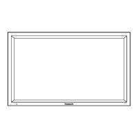
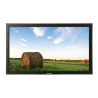
TH-50PF11UK
9.1.2. Initialization Pulse Adjust
1. Set Aging pattern (white pattern signal) by IIC mode.
2. Set the picture controls as follows.
Picture menu: Standard
Picture: +25
Aspect: Full
3. Connect Oscilloscope to TPSC1 and adjust VR16602 for 250V ± 10V.
9.1.3. P.C.B. (Print Circuit Board) exchange
9.1.3.1. Caution
1. To remove P.C.B., wait 1 minute after power was off for discharge from electrolysis capacitors.
9.1.3.2. Quick adjustment after P.C.B. exchange
Adjust the following voltages with the multimeter.
*See the Panel Label.
Caution
Absolutely do not reduce Vsus voltage below Ve not to damage the P.C.B.
Test Point Volume Level
TPSC1 (SC) VR16602 (SC) 250V ± 10V
at 100 µ
s period on the down slope.
P.C.B. Name Test Point Voltage Volume Remarks
P Board Vsus TPVSUS Vsus ± 2V VR251 (P) *
SC Board Vad TPVAD -140V ± 1V VR16600 (SC)
Vscn TPVSCN Vad + 145V ± 4V Fixed
Vset TPVSET 325V + 7V, -9V Fixed
SS Board Ve TPVE Ve ± 1V VR16000 (SS) *
Vda TPVDA 75V + 1V, -2V Fixed
D, DS Board White balance and Sub brightness for NTSC, PAL, HD, PC and 625i signals
DN Board Set Market Select Number to correct destination by MS mode (See chap. 6.1.4)
 Loading...