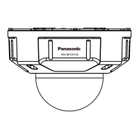
WV-SFV531
Installation Guide
Network Camera
in China
● This manual describes the installation procedures, network camera installation, cable connec-
tions, and the angle of view adjustment.
● Before reading this manual, be sure to read the Important Information.
Parts and functions
The component names of the camera are as follows. Refer to the illustration when installing or
adjusting the camera.
Standard accessories Making connections
Important Information ............................... 1 pc.
Installation Guide (this document) ............ 1 set
Warranty card ........................................... 1 set
CD-ROM*
1
................................................ 1 pc.
Code label*
2
.............................................. 1 pc.
*1 The CD-ROM contains the operating instructions and different kinds of tool software pro-
grams.
*2 This label may be required for network management. The network administrator shall retain
the code label.
The following parts are used during installation procedures.
Ⓐ Attachment plate .................................. 1 pc.
Ⓑ Base bracket........................................ 1 pc.
Ⓒ Fixing screws for attachment plate
(M4 × 8 mm) ...................................... 5 pcs.
(of them, 1 for spare)
Ⓓ 4P alarm cable ..................................... 1 pc.
Ⓔ MONITOR OUT conversion plug ......... 1 pc.
Ⓕ
Template A (for the attachment plate)
. 1 sheet
Ⓖ Template B (for the base bracket) ... 1 sheet
Ⓗ Bit (Hex wrench, screw size 6.35 mm
{1/4 inches} T20) ................................. 1 pc.
Ⓘ 2P power cable .................................... 1 pc.
Ⓙ LAN connector cover ........................... 1 pc.
Ⓚ Waterproof tape ................................... 1 pc.
Ⓛ Auxiliary handle ................................... 1 pc.
Ⓗ Ⓚ
●
How to initialize the camera
Follow the steps below to initialize the network camera.
q
Turn o the power of the camera. When using a PoE hub, disconnect the LAN cable from the camera.
When using an external power supply, disconnect the 2P power cable plug from the camera.
w
Turn on the power of the camera while holding down the INITIAL SET button, and keep the INITIAL
SET button held down till the SD MOUNT indicator is lit in green (more than 10 seconds). In
about 2 minutes after releasing the INITIAL SET button, the camera will start up and the settings
including the network settings will be initialized.
● When data is being sent via the network camera Blinks green (accessing)
Turn off each system’s power supply before making a connection. Before making connections,
prepare the required peripheral devices and cables.
* Use a LAN cable (category 5e or better, 8 pins, straight).
● When the camera is able to communicate with the Lights orange
connected device
● When an SD memory card*
1
is inserted and could Lights off → Blinks green →
be recognized Lights off
● When data can be saved after the SD memory card is Lights off → Lights green
inserted and the SD ON/OFF button is pressed
(less than 1 second)
● When data can be saved to the SD memory card Lights green
● When the SD memory card is removed after holding
Lights green → Blinks green →
down the SD ON/OFF button (about 2 seconds)
Lights off (recording)
Lights green → Lights off
(waiting for recording)
● When data cannot be saved to the SD memory card
Lights off
because an abnormality was detected or the SD
memory card is configured not to be used
IMPORTANT:
● When the camera is initialized, the settings including the network settings will be initial-
ized. Note that the CRT key (SSL encryption key) used for the HTTPS protocol will not be
initialized.
● Before initializing the settings, it is recommended to write down the settings in advance.
● Do not turn off the power of the camera during the process of initialization. Otherwise, it
may fail to initialize and may cause malfunction.
IMPORTANT:
● Use all 4 pairs (8 pins) of the LAN cable (category 5e or better, straight).
● The maximum cable length is 100 m {328 feet}.
● Make sure that the PoE device in use is compliant with IEEE802.3af standard.
● When connecting both the 12 V DC power supply and the PoE device for power sup-
ply, 12 V DC will be used for power supply*.
* If a 12 V DC power supply and a PoE hub or router are used at the same time, net-
work connections may not be possible. In this case, disable the PoE settings.
Refer to the operating instructions of the PoE hub or router in use.
* In the situation where a 12 V DC power supply and a PoE hub or router are used at the
same time and the 12 V DC power supply is then disconnected, the power supply may
be stopped and the camera may restart depending on the PoE hub or router used.
● When the LAN cable is disconnected once, reconnect the cable after around 2 seconds.
When the cable is quickly reconnected, the power may not be supplied from the PoE device.
● When cables are used outdoors, there is a chance that they may be affected by lightning.
In this case, install a lightning arrester just before where the cables connect to the camera.
Connect a LAN cable to the RJ45 (female) network cable
Waterproof treatment for the cable joint sections
When connecting to a network using a PoE hub
Microphone/line input cable
Connect a stereo mini plug (ø3.5 mm).
● Input impedance: Approx. 2 kΩ (unbalanced)
● Recommended cable length: Less than 1 m {3.28 feet} (for microphone input)
Less than 10 m {32.8 feet} (for line input)
● Recommended microphone: Plug-in power type (option)
● Supply voltage: 2.5 V ±0.5 V
● Recommended sensitivity of microphone: –48 dB ±3 dB (0 dB=1 V/Pa,1 kHz)
● Input level for the line input: Approx. –10 dBV
IMPORTANT:
● Be sure to use the
Ⓓ
4P alarm cable (accessory) provided with this product.
● When using the EXT I/O terminals as the output terminals, ensure they do not cause
signal collision with external signals.
● Install external devices so that they do not exceed the ratings above.
Connect the alarm input/output cable
<Ratings>
• ALARM IN1(DAY/NIGHT IN), ALARM IN2, ALARM IN3
Input specication: No-voltage make contact input (4 V - 5 V DC, internally pulled up)
OFF: Open or 4 V - 5 V DC
ON: Make contact with GND (required drive current: 1 mA or more)
• ALARM OUT, AUX OUT
Output specication: Open collector output (maximum applied voltage: 20 V DC)
Open: 4 V - 5 V DC by internal pull-up
Close: Output voltage 1 V DC or less (maximum drive current: 50 mA)
* The default of EXT I/O terminals is “O”.
Connect an external amplifier-embedded speaker to the audio output cable
Connect a stereo mini plug (ø3.5 mm).
● Output impedance: Approx. 600 Ω (unbalanced)
● Recommended cable length: Less than 10 m {32.8 feet}
● Output level: –20 dBV
IMPORTANT:
● Connect/disconnect the audio cables and turn on the power of the camera after turn-
ing off the power of the audio output devices. Otherwise, loud noise may be heard
from the speaker.
● Make sure that the stereo mini plug is connected to this cable. When a monaural mini
plug is connected, audio may not be heard.
When connecting a monaural speaker with amplifier, use a locally procured conver-
sion cable (mono-stereo).
Adequate waterproof treatment is required for the cables when installing the camera with cables
exposed or installing it under the eaves. The camera body is waterproof, but the cable ends are
not waterproof.
Be sure to use the supplied waterproof tape at the points where the cables are connected to ap-
ply waterproof treatment in the following procedure. Failure to observe this or use of a tape other
than the Ⓚ waterproof tape (accessory) (such as a vinyl tape) may cause water leakage resulting
in malfunction.
Before starting the installation, check the entire system conguration. The following illustration
gives a wiring example of how to connect the camera to the network via a PoE device (hub).
<LAN cable> < Alarm input/output cable, power cable, micro-
phone/line input cable, audio output cable>
IMPORTANT:
● Also waterproof the
Ⓘ
2P power cable (accessory),
Ⓓ
4P alarm cable (accessory), and external connections
in the same way.
● Stretch the tape by approx. twice (see the illustration)
and wind it around the cable. Insufficient tape stretch
causes insufficient waterproofing.
● To prevent the LAN cable hook from coming loose
easily, fit the
Ⓙ
LAN connector cover (accessory)
onto the pigtail cable as illustrated, and then slide it in
the direction indicated by the arrow.
The connector of the LAN cable used with this cam-
era must meet the following restrictions.
Height when inserted (From bottom to hook.):
Max. 16 mm {5/8 inches}
Connector width: Max. 14 mm {9/16 inches}
● To install this product outdoors, be sure to waterproof
the cables. Waterproof grade (IEC IP66 or equivalent) is
applied to this product only when it is installed correctly
as described in these operating instructions and appro-
priate waterproof treatment is applied. The internal parts
of
Ⓑ
base brackets (accessory) are not waterproofed.
2x
IMPORTANT:
● The adjustment monitor is used for checking the adjustment of the angular field of view
when installing the camera or when servicing. It is not provided for recording/monitoring use.
● Depending on the monitor, some characters (camera title, preset ID, etc.) may not be
displayed on the screen.
● Use a switching hub or a router which is compliant with 10BASE-T/100BASE-TX.
● If a PoE hub is not used, each network camera must be connected to a 12 V DC
power supply.
● When using 12 V DC, power supply from a PoE hub or router is not required.
INITIAL SET button (Initializing / NTSC
PAL switch button)
Dehumidifying
device
Auto focus
(
AF
)
button
•
FRONT must posi-
tioned in front of the
camera (on the
Panasonic logo side).
Direction marker
for installation
(FRONT
)
Ⓙ
LAN connector cover (accessory)
Wind the tape in a
half-overlapping
manner.
Wind the tape in a
half-overlapping manner.
(Hex wrench, screw size
6.35 mm {1/4 inches} T20)
ACT indicator
SD MOUNT indicator
*1 SDXC/SDHC/SD memory card is described as SD memory card.
*2
Depending on the scanning application used, the Data Matrix may not be able to be
read correctly. In this case, access the site by directly entering the following URL.
http://security.panasonic.com/pss/security/support/qr_sp_select.html
MONITOR OUT terminal
(factory shipment: NTSC
monitor)
Connect the output cable of the AC adaptor to the
Ⓘ
2P power cable (accessory).
Power cable
12 V DC
Red Positive
Black Negative
<Required cable>
LAN cable (category 5e or better, straight)
Use a LAN cable (category 5e or better, cross) when directly connecting the camera to a PC.
* Recommended cable length from the speaker: less than 10 m {32.8 feet}
Recommended cable length from the microphone: less than 1 m {3.28 feet}
For U.S. and Canada:
Panasonic System Communications
Company of North America,
Unit of Panasonic Corporation
of North America
www.panasonic.com/business/
For customer support, call 1.800.528.6747
Two Riverfront Plaza, Newark, NJ 07102-5490
Panasonic Canada Inc.
5770 Ambler Drive, Mississauga,
Ontario, L4W 2T3 Canada
(905)624-5010
www.panasonic.ca
For Europe and other countries:
Panasonic Corporation
http://www.panasonic.com
Panasonic Corporation
Osaka, Japan
Authorised Representative in EU:
Panasonic Testing Centre
Panasonic Marketing Europe GmbH
Winsbergring 15, 22525 Hamburg, Germany
Connect the power cable
IMPORTANT:
● The 12 V DC power supply shall be insulated from the commercial AC power.
● Be sure to use the
Ⓘ
2P power cable (accessory) provided with this product.
● Be sure to fully insert the
Ⓘ
2P power cable (accessory) into the 12 V DC power
supply terminal. Otherwise, it may damage the camera or cause malfunction.
● When installing the camera, make sure that excessive force is not applied to the power cable.
● Be sure to use an AC adaptor compliant with the Specifications (written in the indication
label on the bottom side of this unit) regarding power source and power consumption.
Caution:
● A READILY ACCESSIBLE DISCONNECT DEVICE SHALL
BE INCORPORATED TO THE EQUIPMENT POWERED
BY 12 V DC POWER SUPPLY.
● ONLY CONNECT 12 V DC CLASS 2 POWER SUPPLY (UL
1310/CSA 223) or LIMITED POWER SOURCE (IEC/EN/
UL/CSA 60950-1).
Included Installation Instructions
© Panasonic Corporation 2017
Ⓓ
4P alarm cable (accessory)
GND (black)
ALARM IN3, AUX OUT, DAY (gray) (Alarm input 3, AUX output switching output)
ALARM IN2, ALARM OUT (red) (Alarm input 2, Alarm output)
ALARM IN1, DAY/NIGHT IN (green) (Alarm input 1/DAY/NIGHT switching input)
Stretch the tape to
about twice.
Max. width
Max. height
Powered speaker
Adjustment monitor
PC
PoE device (hub)
LAN cable
(category 5e or
better, straight)
LAN cable
(category 5e or
better, straight)
LAN cable
(category 5e or
better, straight)
Adjustment monitor
Recommended total
extended cable length*
Powered speaker
Microphone
Microphone
SD slot
SD ON/OFF button
●
Points up when installing to a wall.
●
When the INITIAL SET button (i.e. the initializing button) is pressed (less than 1 second)
to
switch the output signal of the MONITOR OUT terminal (NTSCPAL output), the MONITOR
OUT terminal can be switched for the NTSC monitor/PAL monitor.
Dome cover
Tilting table
Panning table
Camera fixing screw
Ⓒ
Fixing screws for
attachment plate
(accessory)
Enclosure Camera
Inner
cover
Ⓐ
Attachment
plate (accessory)
Ⓑ
Base bracket
(accessory)
Conduit wiring
connector
Note:
● Lighting/blinking LED can be turned off with the software settings at any time. (The initial
state is lighting or blinking.) Set the LED to be solid off if necessary, depending on the
installation conditions. (
☞
Operating instructions included in the CD-ROM)
Ⓚ
Waterproof tape
(accessory)
Ⓚ
Waterproof tape
(accessory)
Note:
● Off, input, and output of the external I/O terminal 2 and 3 can be switched by config-
uring the setting. Refer to the operating instructions on the provided CD-ROM for fur-
ther information about the EXT I/O terminal 2 and 3 (ALARM IN2, 3) settings (“Off”,
“Alarm input”, “Alarm output” or “AUX output”).
Ⓘ
2P power cable
(accessory)
RJ45 (female)
Network cable
Alarm input/output cable
Microphone/line input cable (white)
Audio output cable (black)
LAN cable (category 5e
or better, straight)
Ⓓ
4P alarm cable
(accessory)
12 V DC power
supply terminal
12 V DC (red)
GND (black)
Screen display
top (TOP)
Model No. WV-SFV531
● When AF (Auto Focus) operation is being executed Blinks red (Interval of 1 time/ second)
● When the set is being started Lights red
● When an SD memory card is recognized normally Lights red → Lights off
●
When an abnormality is detected in SD card or the SD
Lights red → Stays red
slot is not used after the camera has started
SD ERROR/AF indicator
Two-dimensional barcode
(
Data Matrix
)
:
To our website
*
2
Pan table fixing
screw with washer
Ⓛ
Zoom knob
Auxiliary
handle
LINK indicator
The hook engages with
the connector terminal
Water-proof rubber
Direction marker for installation
(
TOP
)
PGQX1907XA sL0615-3047 Printed