31
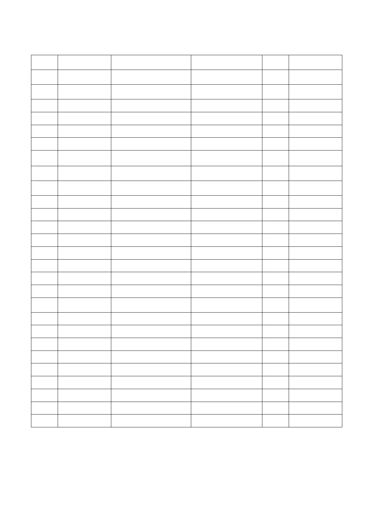
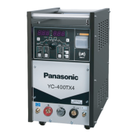
12.2 YC-400TX4Partsdiagram
The No. column and digital S/N are in accordance with the same on parts configuration diagram.
Numb
er
Symbol Part Name Part Number
Quantit
y
Remarks
1 MCB Power switch
NDM1-63C50/3
1
2 PCB2 PC Board(Operation)
WTYET10005-□□
1
3 PCB1 Pc board(Control) WTYET10004-□□ 1
4 CO1 Torch switch socket MT25B2P 1
5 + coupling devices KDZ70-R 1
6 - coupling devices KDZ70-K 1
7
Fu4、FU5、
FU6
FUSE 61NR030H 3
8 Tr1 Control Transformer
TSMU0141□□
TSMU0186-□□
1
9 Tr2 Control Transformer
TSMU0220□□
TSMU0188-□□
1
10
Fu1、Fu2
FUSE 660GH63ULTC 2
11 FAN Cooling fan 200FZY6-S 1
12 D1 Diode MDS60-16W 1
13 C11,C12 Electrolytic Capacitor MKP-LS20UF800V 2
14 C4 Capacitor MKP-C20UF350VDC 1
15 Q1,2 IGBT SKM75GB12T4 2
16 Th switch US-602KXTMQL-83 1
17 SOL gas valve J540-745G 1
18 MTr Main transformer
TSMT0020-□□(380v)
TSMTU063-□□(415v)
1
19 DCL DC choke TSMLU009-□□ 1
20 CC Coupling coil TSMTU014-□□ 1
21 PCB3 Drive PC Board TSM9515□ 1
22 R9 Resistor SFW20A151 1
23 PCB4 Pc board (HF generator) TSM9494□ 1
24 CT CT L03S400D15WM 1
25 FS Flow Switch SSALFW01 1
26 R5,6 Resistor RX274H40W5R0JW 2
27
D2、D3
Diode MMF300YB050U 2



 To Next Page