10
0
1
2
345
6
1/2 1/2 1/2 1/2 1/2 1/2
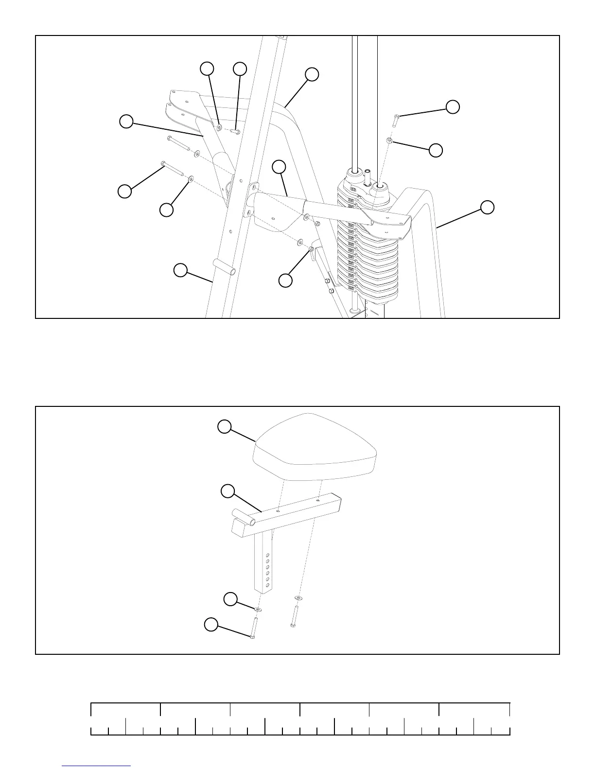
STEP 7:
STEP 8:
• SECURELY assemble one SEAT PAD (16) to the SEAT ADJUST (3) using two 3/8 X 3” BOLTS (67) and two 3/8” WASHERS (64).
See FIGURE 8.
FIGURE 8
FIGURE 7
• LOOSELY assemble the RIGHT and LEFT ARMS (6 & 7) to the RIGHT & LEFT ARM SUPPORTS (4 & 5) using two
3/8 x 3/4” LOCTITE BOLTS (71) and two 3/8” CURVED WASHERS (70)
64
3/8 X 4-1/4”
3/8 X 3”
64
3
16
5
63
7
68
70
2
71
70
71
4
6
• LOOSELY assemble the RIGHT and LEFT ARMS (6 & 7) to the UPRIGHT (2) and the RIGHT and LEFT ARM SUPPORTS
(4 & 5) using two 3/8 X 4-1/4” BOLTS (68), four 3/8” FLAT WASHERS (64), and two 3/8” LOCK NUTS (63). See FIGURE 7.
67
3/8 X 3/4” LOCTITE