9
STEP 5:
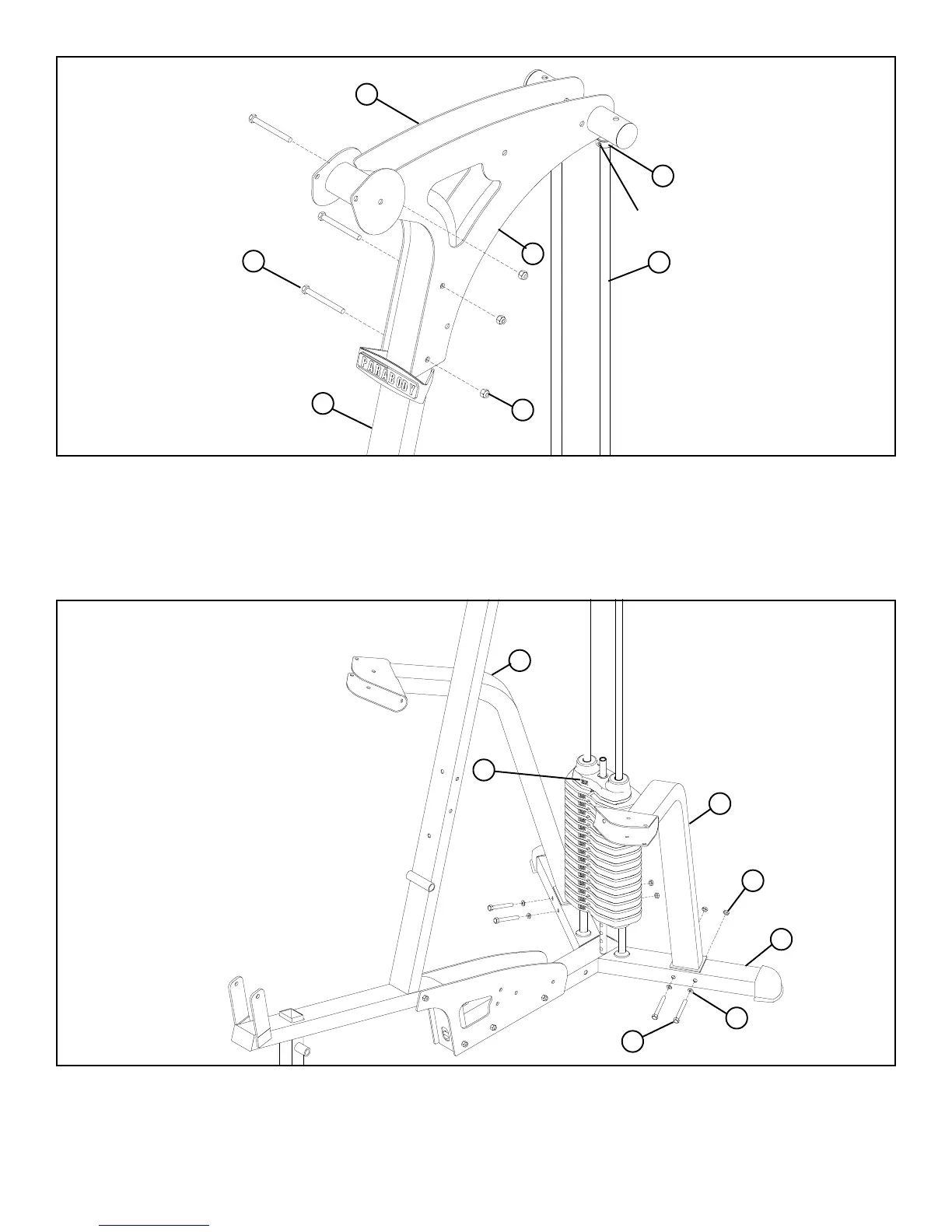
• Swing the GUIDE RODS (18) into the guide rod bushings in each of the RIGHT and LEFT BOOM PLATES (14 & 15) as shown in
FIGURE 5.
• LOOSELY assemble the RIGHT and LEFT BOOM PLATES (14 & 15) to the UPRIGHT (2) using three 3/8 X 3-3/4” BOLTS (57) and
three 3/8” LOCK NUTS (63). See FIGURE 5.
STEP 6:
• LOOSELY assemble the RIGHT and LEFT ARM SUPPORTS (4 & 5) to the BASE (1) using four 3/8 X 3-3/4” BOLTS (57), four
3/8” FLAT WASHERS (64), and four 3/8” LOCK NUTS (63). See FIGURE 6.
3/8 X 3-3/4” 57
2
63
18
14
FIGURE 6
1
63
5
4
FIGURE 5
3/8 X 3-3/4” 57
64
15
• Slide the SHAFT COLLARS (36) to the top of the GUIDE RODS (18) and tighten set screws as shown in FIGURE 5.
TIGHTEN!
36
25
• Apply WEIGHT STACK LABELS (25) to the WEIGHT PLATES (21) starting on the HEAD PLATE as shown in FIGURE 6.