

B
Beth KennedySep 3, 2025
What to do if the message 'AIS at DTE' appears on Paradyne 3160?
- HHeather TaylorSep 3, 2025
If the Paradyne Network Hardware displays the message 'AIS at DTE', check the DTE.
What to do if the message 'AIS at DTE' appears on Paradyne 3160?
If the Paradyne Network Hardware displays the message 'AIS at DTE', check the DTE.
What to do if the message 'AIS at Net' appears on Paradyne 3160 Network Hardware?
If the Paradyne Network Hardware displays the message 'AIS at Net', check the status of the upstream device(s). If problems persist, contact your facility provider.
What to do if the message 'Yellow at DTE' appears on Paradyne Network Hardware?
If the Paradyne Network Hardware displays the message 'Yellow at DTE', check the status of the DTE and ensure that the DTE Drop/Insert (DSX-1) cable is securely attached at both ends.
What to do if the message 'Yellow at Net' appears on Paradyne 3160?
If the Paradyne Network Hardware displays the message 'Yellow at Net', check that your network cable is securely attached at both ends. Also, check the status of the far-end device. If the problem persists, contact your facility provider.
What to do if the message 'OOF at DTE' appears on Paradyne 3160 Network Hardware?
If the Paradyne Network Hardware displays the message 'OOF at DTE', check that the framing format for the DTE Drop/Insert (DSX-1) interface is correct. Also, ensure the DTE Drop/Insert (DSX-1) cable is securely attached at both ends.
What to do if the message 'OOF at Net' appears on Paradyne 3160 Network Hardware?
If the Paradyne Network Hardware displays the message 'OOF at Net', verify that the framing format for the network interface is correct and ensure the network cable is securely attached at both ends. If problems persist, contact your facility provider.
What to do if the message 'LOS at DTE' appears on Paradyne 3160 Network Hardware?
If the Paradyne Network Hardware displays the message 'LOS at DTE', check that the DTE Drop/Insert (DSX-1) cable is securely attached at both ends. Also, check the DTE status.
What to do if the message 'LOS at NET' appears on Paradyne Network Hardware?
If the Paradyne Network Hardware displays the message 'LOS at NET', check that the network cable is securely attached at both ends and check the far-end status. If the issue persists, contact your facility provider.
Describes the ACCULINK 316x DSU/CSU's function as an interface between T1 networks and customer equipment.
Lists key features of the DSU/CSU, including software configuration and loopback capabilities.
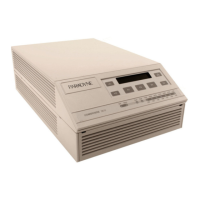
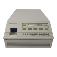
Details the physical characteristics of the ACCULINK 316x series DSU/CSUs, including front and rear panels.
Introduces the chapter covering standalone DSU/CSU installation, examples, cabling, and power-up procedures.
Illustrates common applications for the DSU/CSU in network interconnection scenarios.
Explains the automatic self-test performed by the DSU/CSU upon power-up or reset.
Introduces the chapter detailing DSU/CSU operations, including front panel use and configuration.
Explains how to interact with the DSU/CSU's front panel LCD, keypad, and LEDs.
Covers displaying, editing, and saving DSU/CSU configuration options.
Outlines steps to configure the DSU/CSU for network management access via SNMP or Telnet.
Introduces the chapter on maintenance, fault detection, and diagnostic tests for DSU/CSUs.
Explains how to view the results of the power-up self-test.
Provides guidance for diagnosing and resolving common DSU/CSU problems.
Procedures for performing remote loopback tests to troubleshoot circuits with far-end devices.
Introduces the configuration option tables arranged by functional groups.
Covers configuration options for the DTE Drop/Insert (DSX-1) interface.
Details configuration options for the synchronous data ports (Ports 1-4).
Lists configuration options for the network interface, including framing and coding.
Organizes configuration options for SNMP and Telnet access management.
Introduces the appendix detailing connector pin assignments and cables for DSU/CSU interfaces.
Describes the RJ48C connector and cable for the T1 network interface.
Details the COM port connector and its cables for PC emulation, terminals, or network devices.
Introduces Management Information Base (MIB) objects supported by the DSU/CSU.
Details the groups within MIB II supported by the DSU/CSU.
Covers objects for managing RS-232 interfaces and synchronous data ports.
Introduces IP addressing schemes for network management system scenarios.
Illustrates daisy-chained standalone devices on the same subnet via FDL.
Introduces front panel emulation software for accessing DSU/CSU functionality remotely.
Provides step-by-step instructions for installing the emulation software on a PC.
Guides on launching the emulation software and configuring communication settings.
Introduces asynchronous terminal operation, covering configuration and connection methods.
Explains the three types of async terminal screens and screen function keys.
Explains how to display or change DSU/CSU configuration options via the main menu.
Shows how to enable password protection for the communication port.
| Device Type | ADSL Modem |
|---|---|
| Data Rate | Up to 8 Mbps downstream, up to 1 Mbps upstream |
| Type | External |
| Standards | ANSI T1.413 Issue 2, ITU G.992.1 (G.dmt), ITU G.992.2 (G.lite) |
| Data Rate Downstream | 8 Mbps |
| Data Rate Upstream | 1 Mbps |
| Weight | 0.5 lbs |
| Interface | RJ-11 |