5: BASIC Stamp Command Reference - DTMFOUT
BASIC Stamp Programming Manual 2.0c • www.parallaxinc.com • Page 109
The BASIC Stamp controller is a purely digital device. DTMF tones are
analog waveforms, consisting of a mixture of two sine waves at different
audio frequencies. So how does a digital device generate analog output?
The BASIC Stamp creates and mixes the sine waves mathematically, then
uses the resulting stream of numbers to control the duty cycle of a very
fast pulse-width modulation (PWM) routine. So what’s actually coming
out of the I/O pin is a rapid stream of pulses. The purpose of the filtering
arrangements shown in Figures 5.2 and 5.3 is to smooth out the high-
frequency PWM, leaving only the lower frequency audio behind.
Keep this in mind if you want to interface BASIC Stamp's DTMF output to
radios and other equipment that could be adversely affected by the
presence of high-frequency noise on the input. Make sure to filter the
DTMF output thoroughly. The circuits in Figure 5.2 are only a starting
point; you may want to use an active low-pass filter with a roll-off point
around 2 kHz.
Demo Program (DTMFOUT.bs2)
This demo program is a rudimentary memory dialer. Since DTMF digits fit within a nibble (four
bits), the program below packs two DTMF digits into each byte of three EEPROM data tables.
The end of a phone number is marked by the nibble $F, since this is not a valid phone-dialing
digit.
'{$STAMP BS2} 'STAMP directive (specifies a BS2)
'-----Define variables-----
EEloc VAR BYTE ' EEPROM address of stored number.
EEByte VAR BYTE ' Byte containing two DTMF digits.
NOTE: This is written for the BS2
but can be used for the BS2e,
BS2sx and BS2p also. Locate the
proper source code file or modify
the STAMP directive before
downloading to the BS2e, BS2sx or
BS2p.
2
2
2
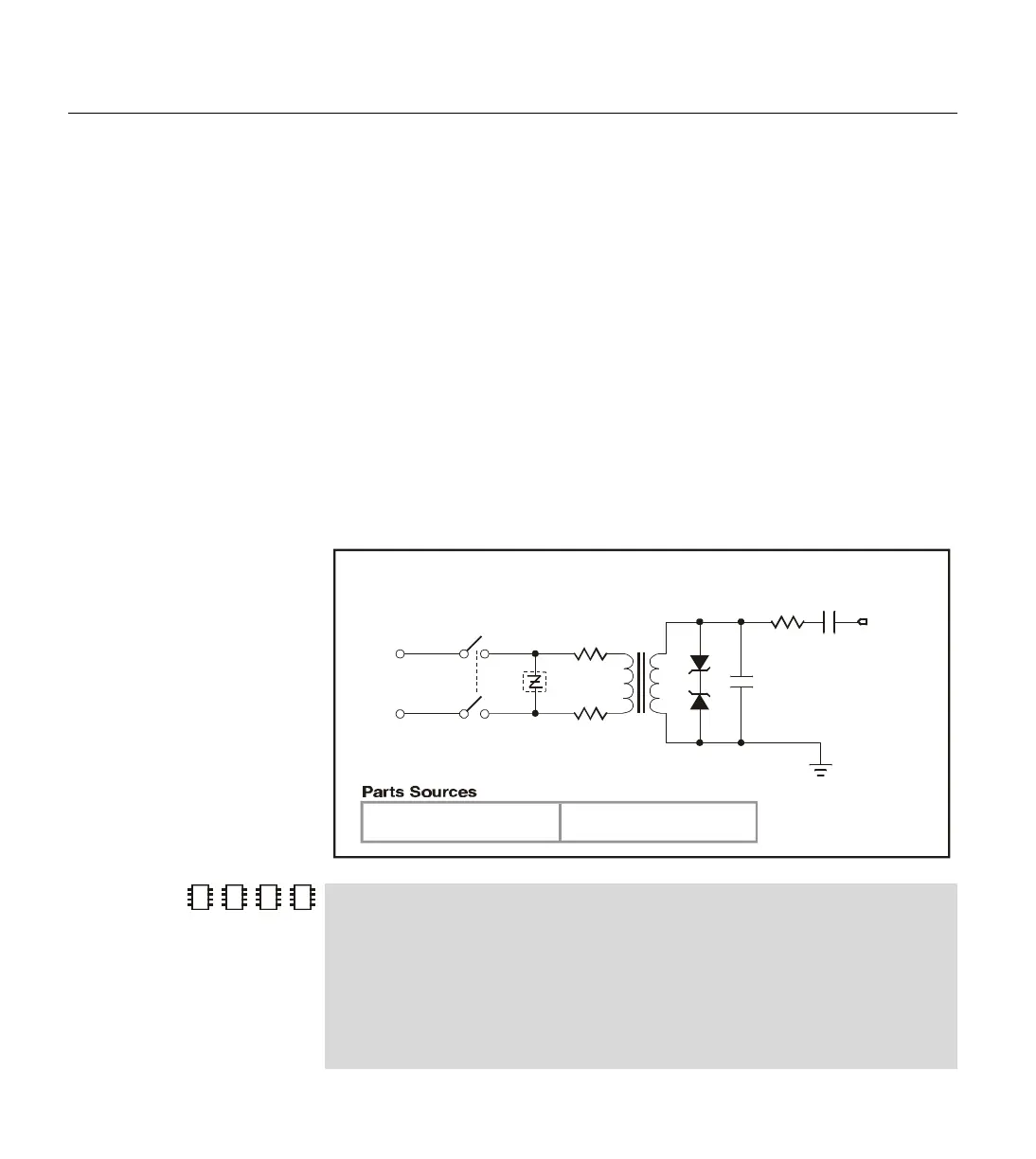
Jameco (JC), 1-800-831-4242
or 415-592-8097
Interfacing to the T elephone Line
600-600
Ω
transformer
(JC: 117760)
270V “Sidactor”
(DK: P3000AA61-ND
P3000AA61-ND)
10
Ω
(both)
3.9V zeners (both)
DK: 1N5228BCT -ND
phone line
(red and g reen)
0.001
µ
F
0.1
µ
F1 k
Ω
connectswitch (or
relay contacts)
Digi-K ey (DK), 1-800-344-4539
or 218-681-6674
from I/O pin
Vss
Figure 5.3: Example DAA Circuit to
Interface to a Standard Telephone
Line.
TECHNICAL BACKGROUND.