5: BASIC Stamp Command Reference – PULSOUT
BASIC Stamp Programming Manual 2.0c • www.parallaxinc.com • Page 243
PULSOUT
BS1 BS2 BS2e BS2sx BS2p
PULSOUT Pin, Period
Function
Generate a pulse on Pin with a width of Period.
• Pin is a variable/constant/expression (0 – 15) that specifies the I/O
pin to use. This pin will be set to output mode.
• Period is a variable/constant/expression (0 – 65535) that specifies
the duration of the pulse. The unit of time for Period is described in
Table 5.63.
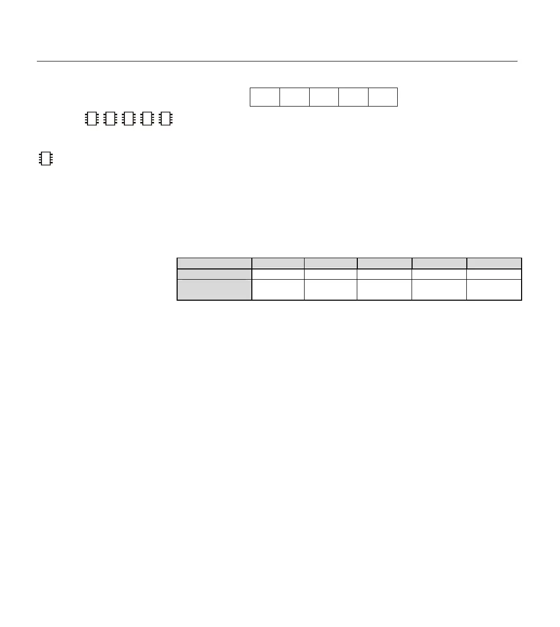
Quick Facts
BS1 BS2 BS2e BS2sx BS2p
Units in Period
10 µs
2 µs 2 µs 0.8 µs 1.18 µs
Maximum pulse
width
655.35 ms 131.07 ms 131.07 ms 52.428 ms 55.479 ms
Explanation
PULSOUT sets Pin to output mode, inverts the state of that pin; waits for
the specified Period; then inverts the state of the pin again; returning the bit
to its original state. The unit of Period is described in Table 5.63. The
following example will generate a 100 us pulse on I/O pin 5 (of the BS2):
PULSOUT 5, 50 ' Generate a pulse on pin 5.
The polarity of the pulse depends on the state of the pin before the
command executes. In the example above, if pin 5 was low, PULSOUT
would produce a positive pulse. If the pin was high, PULSOUT would
produce a negative pulse.
If the pin is an input, the output state bit, OUT5 (PIN5 on the BS1) won’t
necessarily match the state of the pin. What happens then? For example:
pin 7 is an input (DIR7 = 0) and pulled high by a resistor as shown in
Figure 5.26a. Suppose that pin 7 is low when we execute the instruction:
PULSOUT 7, 5 ' Generate a pulse on pin 7.
Figure 5.26b shows the sequence of events on that pin. Initially, pin 7 is
high. Its output driver is turned off (because it is in input mode), so the
2
2
2
NOTE: Expressions are not
allowed as arguments on the BS1.
The range of the Pin argument on
–
Table 5.63: PULSOUT Quick Facts.
CONTROLLING THE POLARITY OF THE
PULSE
.
W
ATCH OUT FOR UNDESIRABLE PULSE
GLITCHES
.