PULSOUT - BASIC Stamp Command Reference
Page 244 • BASIC Stamp Programming Manual 2.0b • www.parallaxinc.com
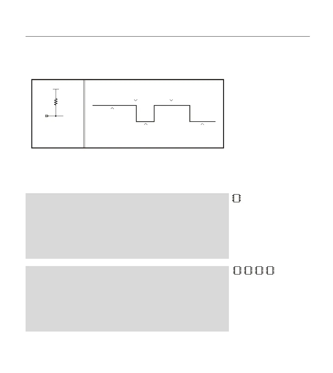
10k resistor sets the state on the pin. When PULSOUT executes, it turns on
the output driver, allowing OUT7 (PIN7 on the BS1) to control the pin.
Since OUT7 (PIN7 on the BS1) is low, the pin goes low. After a few
microseconds of preparation, PULSOUT inverts the state of the pin; from
low to high. It leaves the pin in that state for the specified time (10µs if
using a BS2) and then inverts it again, leaving the pin in its original state.
Demo Program (PULSOUT.bas)
' This program blinks an LED on for 10ms at 1-second intervals. Connect the LED to I/O
' pin 0 as shown in the figure within the NAP command description of the manual.
'{$STAMP BS1} 'STAMP directive (specifies a BS1)
HIGH 0 ' Set the pin high (LED off).
Again:
PULSOUT 0, 1000 ' Flash the LED for 10 ms.
PAUSE 1000 ' Wait one second.
GOTO Again ' Repeat endlessly.
Demo Program (PULSOUT.bs2)
' This program blinks an LED on for 10ms at 1-second intervals. Connect the LED to I/O
' pin 0 as shown in the figure within the NAP command description of the manual.
'{$STAMP BS2} 'STAMP directive (specifies a BS2)
HIGH 0 ' Set the pin high (LED off).
Again:
PULSOUT 0, 5000 ' Flash the LED for 10 ms.
PAUSE 1000 ' Wait one second.
GOTO Again ' Repeat endlessly.
2
2
2
NOTE: This is written for the BS2
but can be used for the BS2e,
BS2sx and BS2p also. Locate the
proper source code file or modify
the STAMP directive before
downloading to the BS2e, BS2sx or
BS2p. Keep in mind that the unit of
time may be different than what
appears in the comments here.
ab
Vdd
10 k
Ω
P7
(instruction
executes)
PULSOUT 7,5
positive pulse
O-scope
pin 7 can be connected to an
oscilloscope as shown to
view the results shown on
the right
pin 7 in input mode
(DIR7 = 0,
OUT7 = 0)
but held high by
resistor to Vdd pin changes to
output
pin left as
output - low
(DIR7 = 1,
OUT7 = 0)
Figure 5.26: Example Pulse
Diagram.