2: Quick Start Guide
BASIC Stamp Programming Manual 2.0c • www.parallaxinc.com • Page 29
Quick Start Introduction
This chapter is a quick start guide to connecting the BASIC Stamp to the
PC and programming it. Without even knowing how the BASIC Stamp
functions, you should be able to complete the exercise below. This
exercise assumes you have a BASIC Stamp and one of the development
boards shown in Chapter 1.
Connecting and Downloading
1) If the BASIC Stamp isn't already plugged into your development
board, insert it into the appropriate socket as indicated in the
"Development Boards" section of Chapter 1. Be careful to insert it in
the correct orientation. NOTE: The BASIC Stamp 1 Rev. D is built
into its own development board.
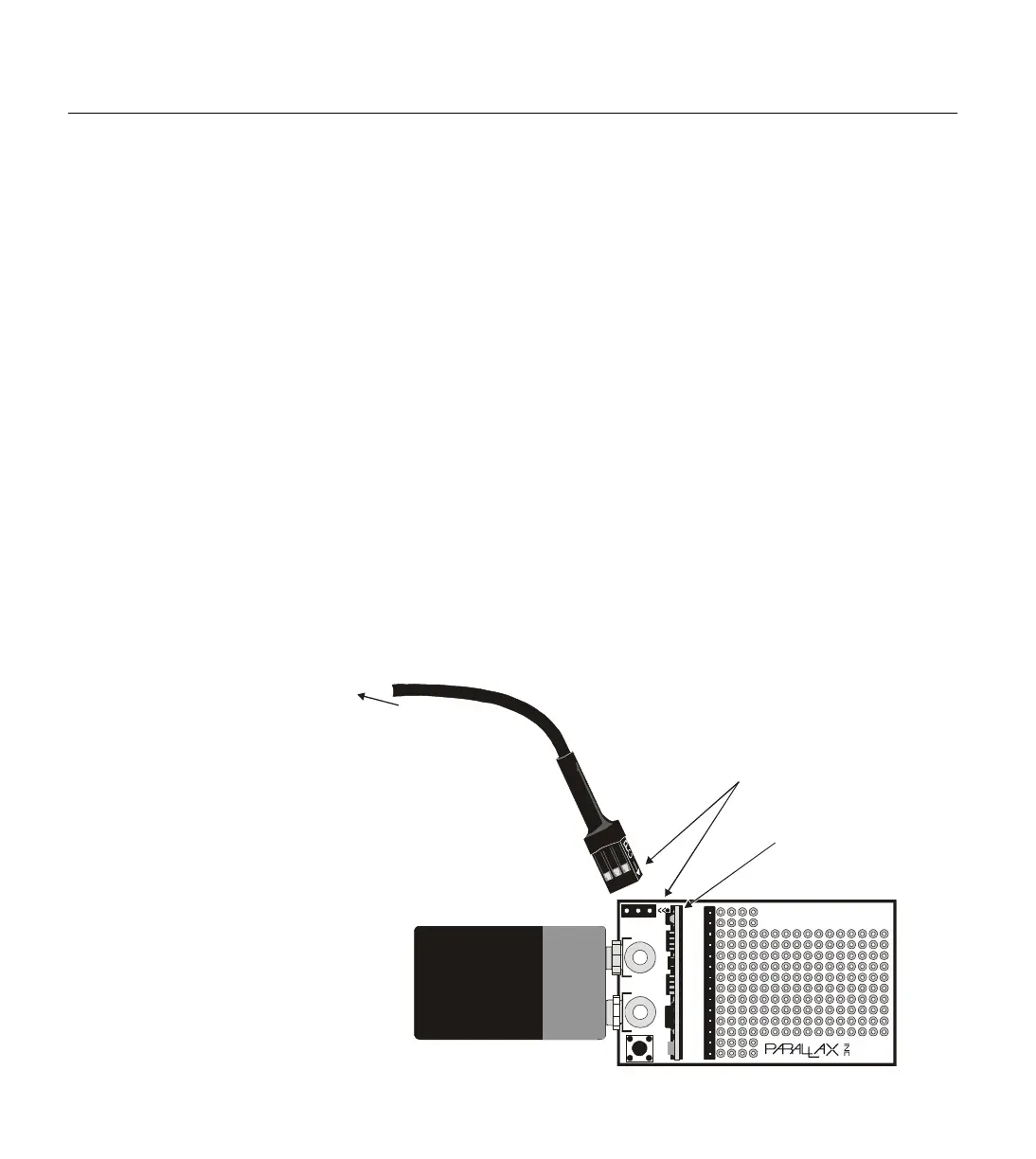
2) If using a BASIC Stamp 1, connect the 25-pin side of your
programming cable to an available parallel port on your computer.
Then connect the 3-pin side to the 3-pin programming header on the
development board. See Figure 2.1 for an example. The 3-pin
connector must be connected so that the arrows on one side of the
plug line up with the arrows "<<" printed on the board.
Alkaline Battery
Powercell
©1994
REV E
TM
Vin
Vss
PCO
PCI
Vdd
RES
P0
P1
P2
P3
P4
P5
P6
P7
BASIC Stamp
ΤΜ
Reset
BS1-IC
2 11 15
PC Parallel Port
Align arrow on plug
to arrows on PC board
25-pin connector
(not shown)
plugs into PC’s
parallel port
BS1-IC properly
plugged into carrier
board (components
facing battery clips)
Figure 2.1: BS1-IC and BASIC
Stamp 1 Carrier Board being
properly connected for
programming. The BS1-IC must be
powered and the 3-pin cable must
be connected in the correct