5: BASIC Stamp Command Reference – I2COUT
BASIC Stamp Programming Manual 2.0c • www.parallaxinc.com • Page 147
Every I
2
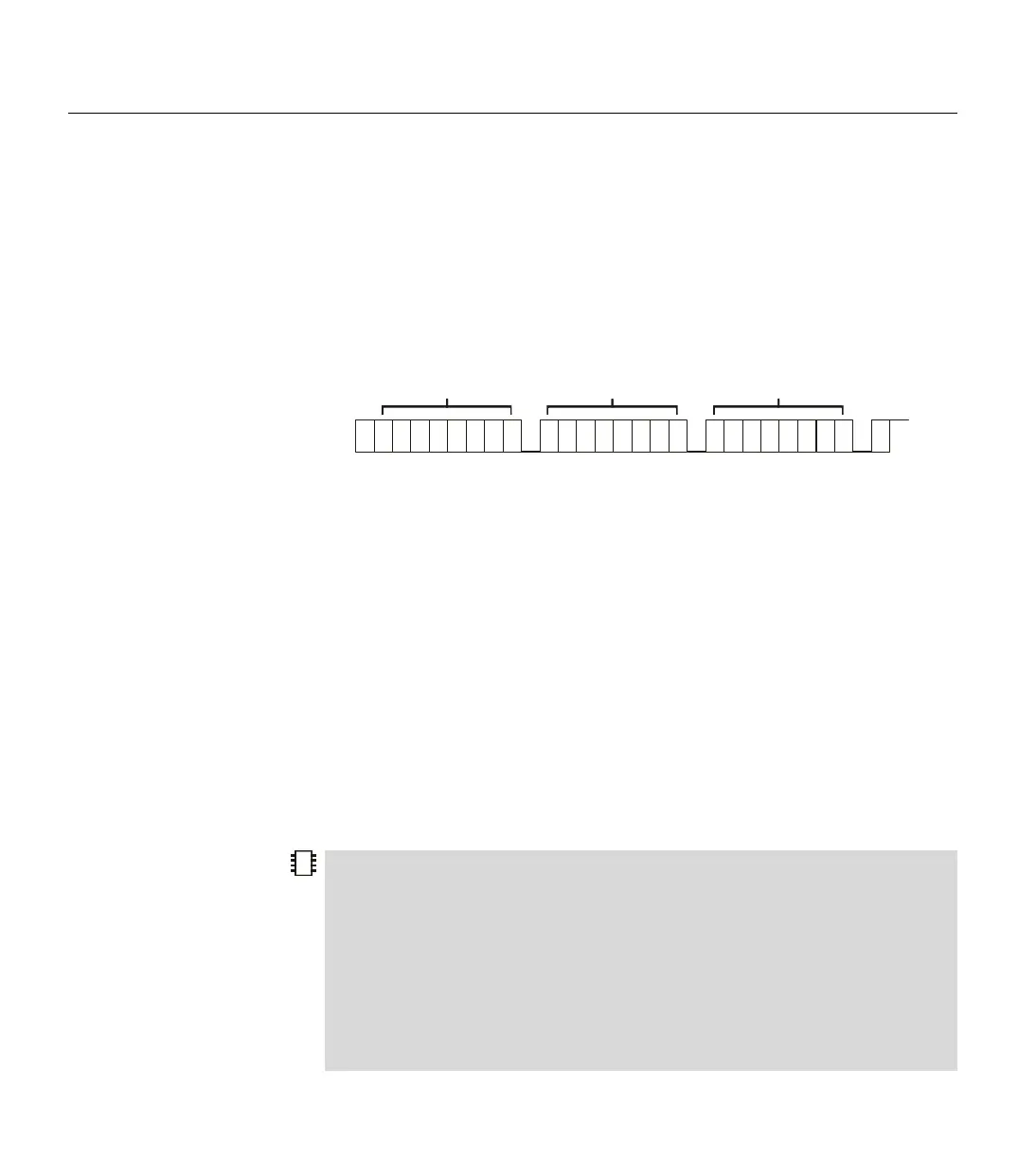
C transmission session begins with a Start Condition and ends
with a Stop Condition. Additionally, immediately after every byte is
transmitted, an extra clock cycle is used to send or receive an
acknowledgment signal (ACK). All of these operations are automatically
taken care of by the I2CIN command so that you need not be concerned
with them. The general I
2
C transmission format is shown in Figure 5.11.
Since the I2COUT command is intended for output only, it actually
overrides the "R/W" bit (bit 0) in the SlaveID argument. This is done to
avoid device conflicts should the value be mistyped. Put simply, this
means commands such as: I2COUT 0, $A0, 10, [0] and I2COUT 0, $A1,
10, [0] both transmit the same thing ($A0, then 10, then the data). Even
though the I2COUT command really doesn't care what the value of the
SlaveID's LSB is, it is suggested that you still set it appropriately for clarity.
Also note that the I2COUT command does not support multiple I
2
C
masters and the BASIC Stamp cannot operate as an I
2
C slave device.
Demo Program (I2C.bsp)
' This program demonstrates writing and reading every location in the 24LC16B EEPROM
' using the BS2p's I2C commands. Connect the BS2p to the 24LC16B DIP EEPROM as
' shown in the diagram in the I2CIN or I2COUT command description.
'{$STAMP BS2p} 'STAMP directive (specifies a BS2p)
Idx VAR WORD 'Index variable for address
Check VAR NIB 'Index for checking returned values
Result VAR BYTE(16) '16-byte array for returned value
WriteToEEPROM:
S
PECIAL NOTE ABOUT I2COUT
INPLIMENTATION
S
P
S
T
A
R
T
SlaveID
A
C
K
Address
A
C
K
Data
A
C
K
S
T
O
P
U
S
F
R
E
E
a
6
a
5
a
4
a
3
a
2
a
1
a
0
rw a
6
a
5
a
4
a
3
a
2
a
1
a
0
a
7
d
6
d
5
d
4
d
3
d
2
d
1
d
0
d
7
NOTES:
S = Start Condition
P = Stop Condition
a = id or address bit
d = data bit (transmitted by the BASIC Stamp or the IC device)
ACK = Acknowledge signal. (Most acknowledge signals are generated by the IC device)
2
2
2
Figure 5.11: I
2
C Transmission
Format.
START AND STOP CONDITIONS AND
ACKNOWLEDGMENTS.