LCDCMD - BASIC Stamp Command Reference
Page 160 • BASIC Stamp Programming Manual 2.0b • www.parallaxinc.com
The above code will send the Scroll Left command (represented by the
number 24) to the LCD whose enable pin is connected to I/O pin 1. This
will cause the LCD display to scroll, or shift, the entire display one
character to the left.
You may have noticed that the Pin argument in the example above was 1.
The LCDCMD command actually uses more than just this I/O pin,
however. The LCDCMD command requires seven I/O pins. This is
because the standard LCD displays have a parallel interface, rather than a
serial one. The Pin argument can be the numbers 0, 1, 8 or 9 and will
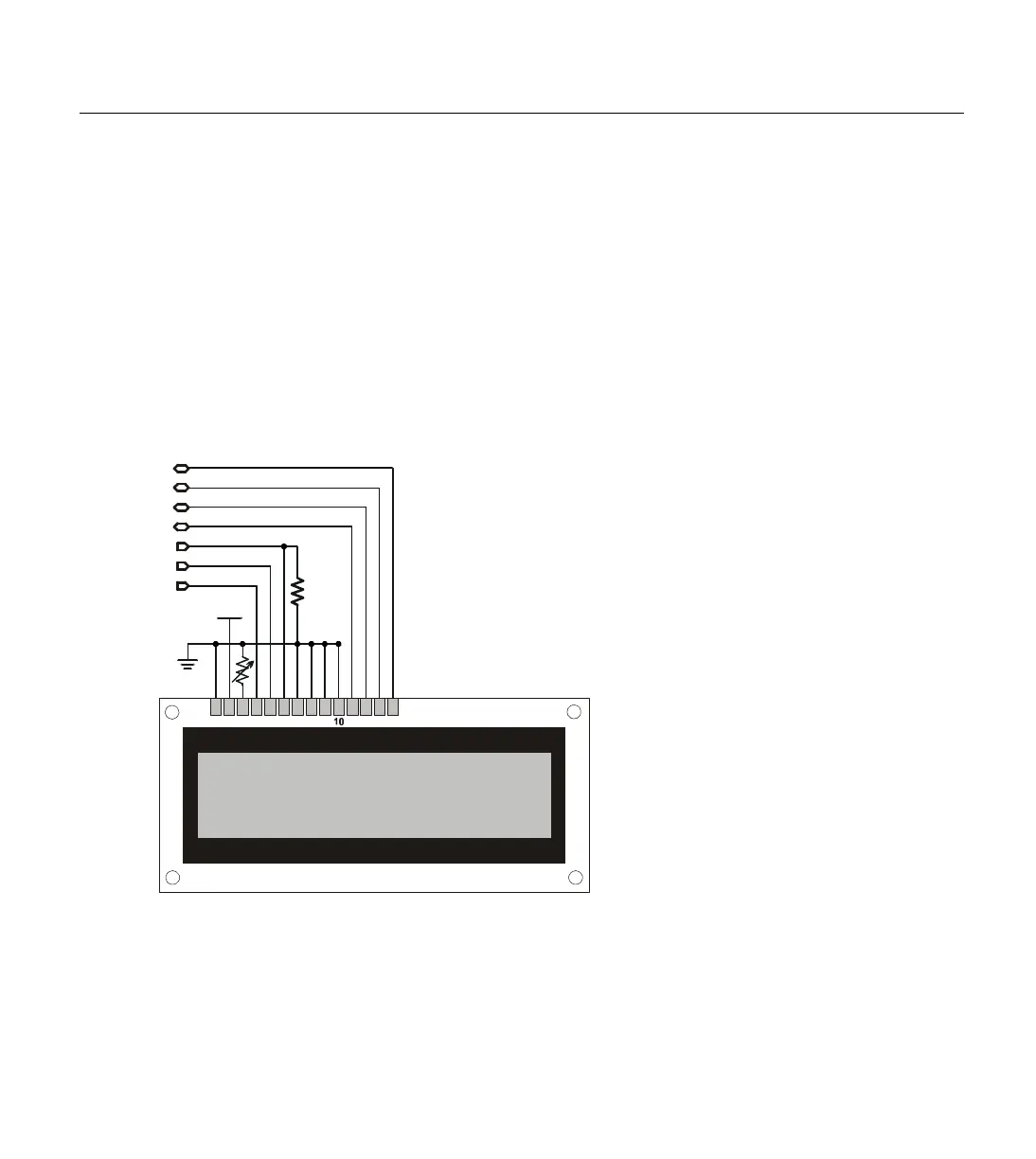
result in the use of the I/O pins shown in Table 5.26. Figure 5.12 shows
the required wiring for the above command to work.
Note that we could have used 0 for the Pin argument and moved the
LCD's Enable pin (pin 6) to I/O pin 0. Similarly, using 9 for the Pin
argument would have required us to wire the LCD's pins to I/O pins 9
through 15, rather than I/O pins 1 through 7.
When the LCD is first powered-up, it will be in an unknown state and
must be properly configured before sending commands like the one
1 2 3 4 5 6 7 8 9 11 12 13 14
Vss
P3
Vdd
10 k
Ω
P2
P1
P4
P5
P6
P7
NOTE: Potentiometer between
LCD pin 3 and ground is for
optional contrast control.
Connect LCD pin 3 directly to
ground for maximum contrast.
RS
R/W
E
DB4
DB5
DB6
Figure 5.12: Example LCD Circuit.
Shown with all connections
necessary for the LCDCMD, LCDIN
and LCDOUT commands.
W
IRING THE BASIC STAMP TO AN
INITIALIZING THE LCD; THE MOST