5: BASIC Stamp Command Reference – POLLOUT
BASIC Stamp Programming Manual 2.0c • www.parallaxinc.com • Page 227
INPUT 0
OUTPUT 1
Loop:
OUT1 = ~IN0
DEBUG "Looping…", CR
OUT1 = ~IN0
GOTO Loop
In this example, we create the inverse relationship of input pin 0 and
output pin 1 manually, in-between the DEBUG and GOTO lines. Though
the effects are the same as when using the polling commands, this
program actually takes a little longer to run and consumes 7 additional
bytes of program (EEPROM) space. Clearly, using the polling commands
is more efficient.
You can have as many polled-input and polled-output pins as you have
available. If multiple polled-output pins are defined, all of them change in
response to changes on the polled-input pins. For example:
POLLIN 0, 1
POLLOUT 1, 0
POLLOUT 2, 1
POLLOUT 3, 1
POLLMODE 2
Loop:
DEBUG "Looping…", CR
GOTO Loop
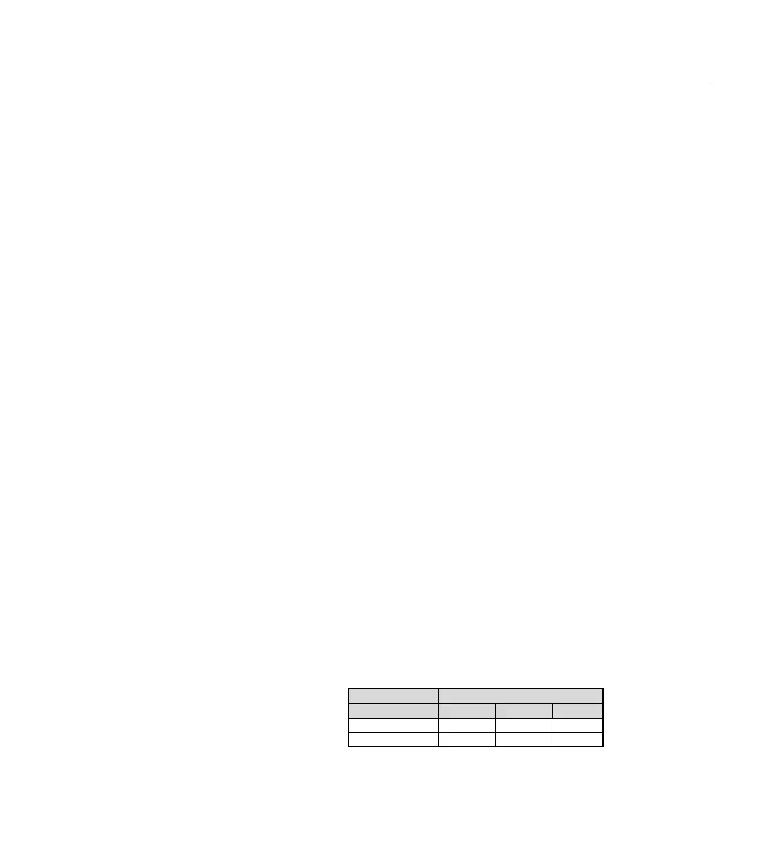
This code sets up I/O pin 0 as a polled-input pin (looking for a high (1)
state) and sets I/O pins 1, 2 and 3 to polled-output pins. Polled-output pin
1 is set to a low-active state and pins 2 and 3 are set to a high-active state.
If I/O pin 0 goes high, the BASIC Stamp will set I/O pin 1 low and I/O
pins 2 and 3 high. The table below shows the two possible states of the
polled-input pin and the corresponding states the BASIC Stamp will set
the polled-output pins to.
Normally, any polled-output pins reflect the state changes continuously,
as described above. The POLLMODE command supports another feature,
Polled-Input Polled-Outputs
0 1 2 3
0 1 0 0
USING MULTIPLE POLLED-INPUT AND
POLLED
-OUTPUT PINS.
POLLED-OUTPUTS CAN BE
LATCHED"
ALSO.
Table 5.58: POLLOUT Truth Table.