1: Introduction to the BASIC Stamps
BASIC Stamp Programming Manual 2.0c • www.parallaxinc.com • Page 21
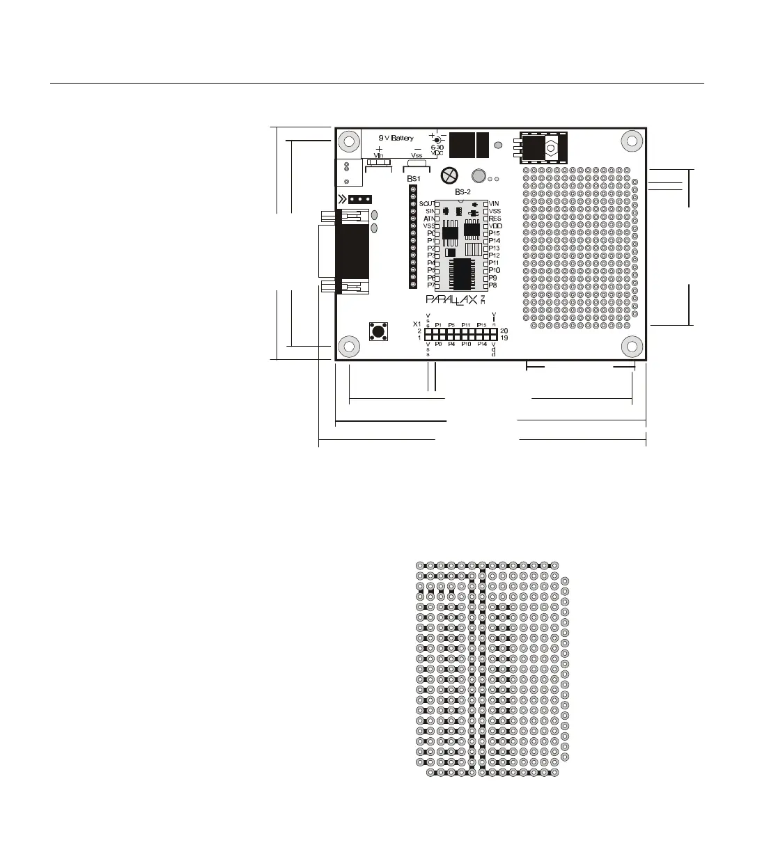
In the prototype area, upper and lower rows as well as two inner columns
of solder pads are connected to Vdd and Vss to provide easy access to
power. IC’s measuring from 0.3” to 0.7” in width can straddle the center
power rails similar to a breadboard. The right-most column of solder pads
is offset to accommodate components like RJ-11 and DB9 connectors.
Figure 1.15: BASIC Stamp Super
Carrier Board (Rev. A) (shown with
BS2-IC properly inserted) (27130)
P15
P14
P13
P12
P11
P10
P9
P8
P7
P6
P5
P4
P3
P2
P1
P0
Vdd
Vdd
Vss
Vss
Vss
Figure 1.16: Prototype area of the
BASIC Stamp Super Carrier Board
(Rev. A) (black lines indicate
interconnected solder pads)
Reset
Pwr
Need Tech Support?
Send email to:
stamptech@parallaxinc.com
Basic Stamp Super Carrier
www.parallaxinc.com (916) 624-8333 ©1999
J3
TM
C2
+
Rev A
C3
J1
C4
P15
P14
P13
P12
P11
P10
P9
P8
P7
P6
P5
P4
P3
P2
P1
P0
Vdd
Vdd
Vss
Vss
Vss
C1
Vin
Vss
PCO
PCI
Vdd
Rst
P0
P1
P2
P3
P4
P5
P6
P7
Vin
J2
Vss
Rocklin, CA - USA
4” (102mm)
4.25” (107mm)
3.25” (94mm)
1.4” (36mm)
0
.
1
”
(
3
m
m
)
3.1” (78mm)
2.7” (70mm)
2.0” (51mm)
0
.
1
”
(
3
m
m
)