5: BASIC Stamp Command Reference – SERIN
BASIC Stamp Programming Manual 2.0c • www.parallaxinc.com • Page 275
RS-232 is the electrical specification for the signals that PC serial ports use.
Unlike normal logic, where a 5 volts is a logic 1 and 0 volts is logic 0, RS-
232 uses -12 volts for logic 1 and +12 volts for logic 0. This specification
allows communication over longer wire lengths without amplification.
Most circuits that work with RS-232 use a line driver/receiver. This
component does two things: (1) it converts the ±12 volts of RS-232 to
TTL-compatible 0 to 5-volt levels and (2) it inverts the relationship of the
voltage levels, so that 5 volts = logic 1 and 0 volts = logic 0.
All BASIC Stamps (except the BS1) have a line receiver on its SIN pin (Rpin
= 16). See the "Hardware" section of the "Introduction to the BASIC
Stamps" chapter. The SIN pin goes to a PC’s serial data-out pin on the DB9
connector built into BASIC Stamp development boards. The connector is
wired to allow both programming and run-time serial communication
(unless you are using the Stamp 2 Carrier Board which is only designed
for programming). For the built-in serial port set the Rpin argument to 16
in the SERIN command.
All BASIC Stamps (including the BS1) can also receive RS-232 data
through any of their I/O pins (Rpin = 0 – 7 for BS1, Rpin = 0 – 15 on all
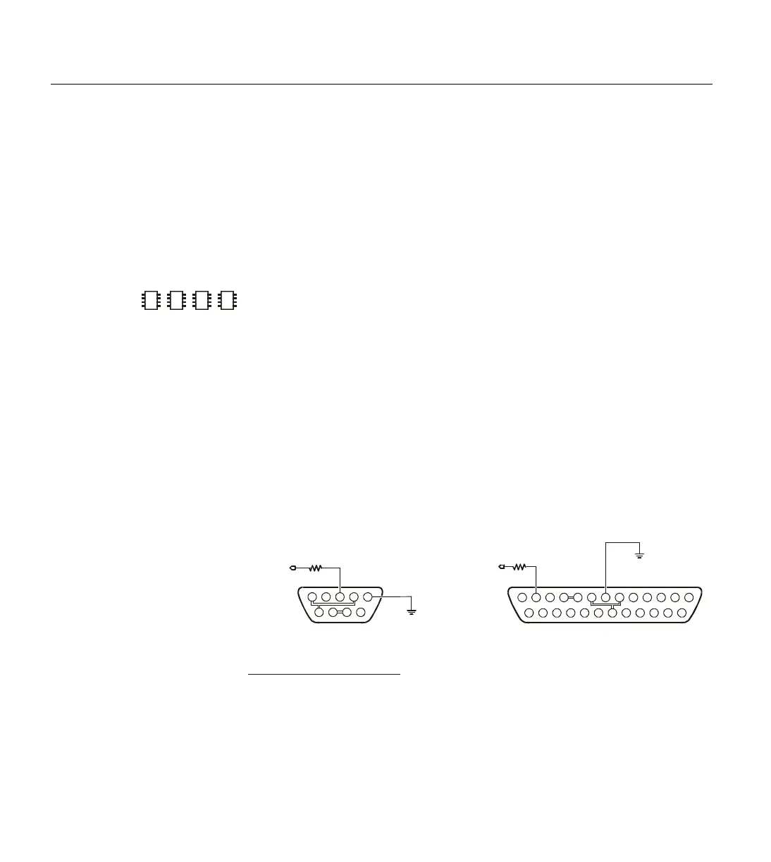
other BASIC Stamps). The I/O pins don’t need a line receiver, just a 22 k
Ω
resistor. The resistor limits current into the I/O pins’ built-in clamping
diodes, which keep input voltages within a safe range. See Figure 5.32
2
2
2
DB-9 Male
(Connector Side)
to I/O pin
22 k
Ω
2
3
4
Transmit Data (TD)
Receive Data (RD)
Request to Send (RTS)
6
7
20
Data Set Ready (DSR)
Signal Ground (SG)
Data Terminal Ready (DTR)
3
2
7
6
5
4
DB25Function DB9
NOTE: The connections shown with double-lines are
normally not necessary. They indicate optional connections
to disable hardware handshaking (DTR-DSR-DCD and
RTS-CTS). This is only necessary if you are using software
or hardware that expects hardware handshaking.
DB-25 Male
(Connector Side)
252423222120191817161514
13121110987654321
9876
54321
Vss
to I/O pin
22 k
Ω
Vss
8Data Carrier Detect (DCD) 1
5Clear to Send (CTS) 8
Figure 5.32: Serial Port Diagram
Showing Correct Connections to a
BASIC Stamp's I/O pin. NOTE:
The 22 k
Ω resister is not required if
connecting to the SIN pin.
USING THE BUILT-IN SERIAL PORT ON
THE
2E
SX AND BS2P.