BASIC Stamp Architecture – Memory Organization
Page 46 • BASIC Stamp Programming Manual 2.0b • www.parallaxinc.com
You may assign other names (symbols) to these RAM registers as shown
in section "Defining and Using Variables", below.
When the BS1 is powered up, or reset, all memory locations are cleared to
0, so all pins are inputs (DIRS = %00000000). Also, if the PBASIC program
sets all the I/O pins to outputs (DIRS = %11111111), then they will initially
output low, since the output latch (PINS) is cleared to all zeros upon
power-up or reset, as well.
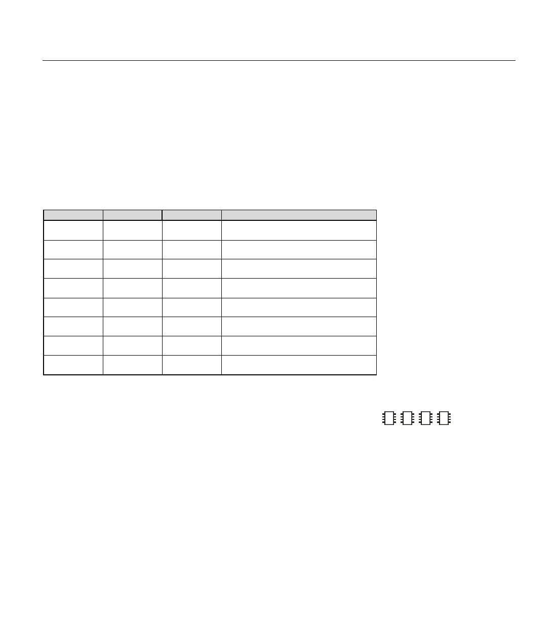
Word Name Byte Names Bit Names Special Notes
PORT
PINS
DIRS
PIN0 – PIN7
DIR0 – DIR7
I/O pins; bit addressable.
I/O pins directions; bit addressable.
W0
B0
B1
BIT0 – BIT7
BIT8 – BIT15
Bit addressable.
Bit addressable.
W1
B2
B3
W2
B4
B5
W3
B6
B7
W4
B8
B9
W5
B10
B11
W6
B12
B13
Used by GOSUB instruction.
Used by GOSUB instruction.
The BS2, BS2e, BS2sx and BS2p have 32 bytes of Variable RAM space
arranged as shown in Table 4.2. Of these, the first six bytes are reserved
for input, output, and direction control of the I/O pins. The remaining 26
bytes are available for general-purpose use as variables.
The word variable INS is unique in that it is read-only. The 16 bits of INS
reflect the state of I/O pins P0 through P15. It may only be read, not
written. OUTS contains the states of the 16 output latches. DIRS controls
the direction (input or output) of each of the 16 I/O pins.
A 0 in a particular DIRS bit makes the corresponding pin an input and a 1
makes the corresponding pin an output. So if bit 5 of DIRS is 0 and bit 6 of
DIRS is 1, then I/O pin 5 (P5) is an input and I/O pin 6 (P6) is an output.
A pin that is an input is at the mercy of circuitry outside the BASIC Stamp;
2
2
2
RAM ORGANIZATION (BS2, BS2E,
BS2
SX, BS2P).
T
HE INPUT/OUTPUT VARIABLES.
Table 4.1: BS1 RAM Organization.
Note: There are eight words,
consisting of two bytes each for a
total of 16 bytes. The bits within the
upper two words are individually
addressable.