Do you have a question about the Parker F12 series and is the answer not in the manual?
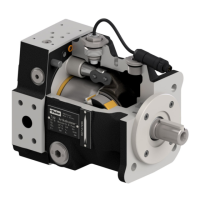
Details on the F12 series bent axis design, frame sizes, and key features.
Diagram illustrating the internal components of the F12 series.
Specifies operating temperature limits for N and FPM shaft seals.
Fasten the unit in a vice and loosen the 4 bolts (item 491).
Remove the barrel housing (item 110), ensuring the valve plate remains in place.
Remove the cylinder barrel (item 411) and take away the shim (item 488).
Remove the barrel support (item 430) from the assembly.
Disassemble the pistons (item 440) from the assembly.
Remove the O-ring (item 221) from the assembly.
Disassemble the retaining ring (item 237).
Remove the seal carrier (item 231).
Remove the O-ring (item 225).
Disassemble the retaining ring (item 478).
Remove the spacer washer (item 476).
Press the shaft (item 311) out of the bearing housing (item 211) using a tube.
Remove the small tapered roller bearing (item 470).
Tap the small bearing ring off using a mandrel.
Tap the large bearing ring off using a mandrel.
Press the shaft (item 311) out of the ring gear (item 452) using a tube and press.
Press bearing (item 460) and ring gear (item 452) onto shaft using press and tube.
Press bearing ring (item 460) into housing (item 211) using a tube.
Press bearing ring (item 470) into housing (item 211) using a tube.
Press bearing (item 470) to set preload, then install spacer washer (item 476).
Install the retaining ring (item 478).
Install the O-ring (item 225).
Install the seal carrier (item 231).
Install the retaining ring (item 237).
Install the O-ring (item 221).
Install the pistons (item 440), lubricating ball sockets.
Install the barrel support (item 430).
Install the shim (item 488).
Install cylinder barrel (item 411) and ensure correct timing marks align.
Grease and install valve plate (item 121) into barrel housing (item 110).
Install barrel housing (item 110), check backlash (0.1-0.3mm) and timing.
Fasten the 4 bolts (item 491) to the specified torque.
Remove the retaining ring (item 237) to access the shaft seal.
Remove the seal carrier (item 231).
Tap the old shaft seal out using a hammer and mandrel.
Tap the new shaft seal back using a tube (65mm OD) and hammer.
Valve plate M provides bi-directional motor operation.
Valve plate L provides left-hand rotation pump operation.
Valve plate R provides right-hand rotation pump operation.
Valve plate G provides LH rotation pump/motor with internal drain.
Valve plate X provides bi-directional pump operation with high self priming.
Press bearing (item 460) and ring gear (item 452) onto shaft using press and tube.
Press bearing (item 470) to achieve correct preload.
Assemble lock washers (item 474) and round nut (item 475), then stake.
Assemble pistons (item 440), lubricating ball sockets prior to assembly.
Install valve plate (item 121) into barrel housing (item 110) ensuring correct placement.
Tap down cylinder barrel (item 411) with retaining ring (item 431) and bearings (item 415).
Assemble shims (item 488) and guide spacer (item 486), aligning spacer to drain port.
Assemble the bearing package with the pistons.
Verify that the timing is correct.
Install shaft seal (item 233) and support ring (item 236), tapping seal down.
Install retaining ring (item 237), lubricating seal before housing assembly.
Assemble bearing housing (item 211), tap down, and torque screws to 220 ± 35 Nm.
Press bearing (item 460) and ring gear (item 452) onto shaft using press and tube.
Press bearing (item 470) to achieve correct preload.
Assemble lock washers (item 474) and round nut (item 475), then stake.
Install shaft seal (item 233) and support ring (item 236), tapping seal down.
Install retaining ring (item 237), lubricating seal before housing assembly.
Tap bearing package into housing (item 211) using a plastic collar and hammer.
Assemble pistons (item 440), lubricating ball sockets prior to assembly.
Assemble bearing (item 425), disc spring (item 433), spacer washer (item 426), retaining ring (item 427).
Assemble spring pins (item 413) and sliding plate (item 424).
Assemble cylinder barrel (item 411) on pistons (item 440) and ensure correct timing.
Install and lubricate O-ring (item 222) on barrel housing (item 481).
Assemble barrel housing, ensuring barrel position, and tap down with hammer.
Install and lubricate O-rings (223, 224) on end cap (item 111).
Place the end cap onto the barrel housing until the O-ring is seated.
Fit a long screw (M12) to spindle and pull up with pliers.
Knock down end cap, fit shims (488) and screws (493), torque to 330 ± 10 Nm.
Install cap screw (item 428) to secure the barrel spindle.
Torque cap screw to 40-45 Nm, then back off 1/3 turn for axial play.
Tap cap screw once to set backlash and ensure it is correct.
Measure drain flow at 500 rpm and 200 bar to check unit condition.
| Brand | Parker |
|---|---|
| Model | F12 series |
| Category | Water Pump |
| Language | English |