Chapter 2 – Installation
11
In the express setup, we will give procedures for the following steps:
1. Connecting the motor to the drive (without a load connected)
2. Connecting AC power to the drive
3. Establishing communications and configuring the drive for autorun
4. Enabling the drive and observing the motor turn
Information you may need for final installation will be presented in Chapter 3
Configuration, in Chapter 4 Special Features, in Appendix A Specifications, and in
the separate Gemini Motor Reference Manual.
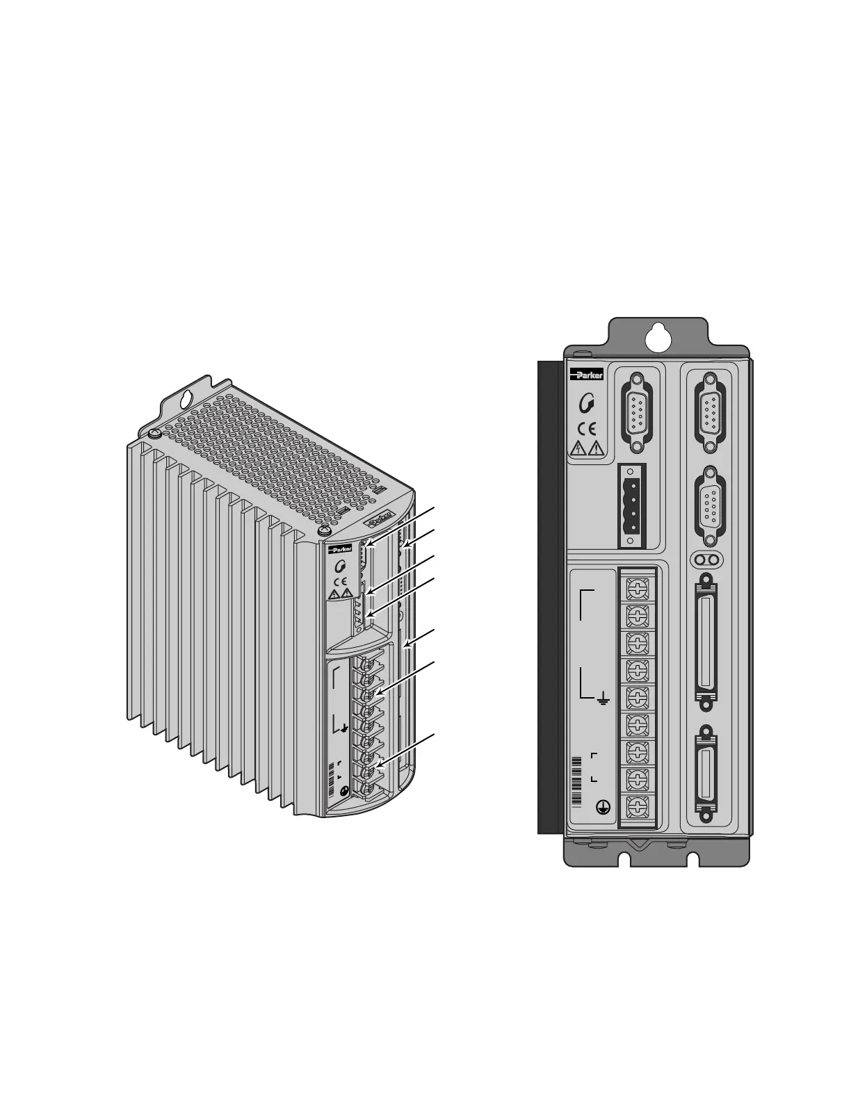
The next drawing shows locations and names of the Gemini components that you
will encounter during the installation procedure.
STEPPER
MOTOR
A+
A–
B+
B–
N/C
N
L1
GT-L5/8
120V
+24V DC
24V RTN
RELAY COM
RELAY N.O.
RS-232/485
C
O
M
P
U
M
O
T
O
R
DRIVE I/O
MOTOR FEEDBACK
DATA BUS OUT
DATA BUS IN
RS-232/485
Relay
Keep Alive Power
Motor Power
AC Power
I/O Connections
Data Bus I/O
+24V DC
24V RTN
RELAY COM
RELAY N.O.
COMPUMOTOR
DATA BUS OUT DRIVE I/O MOTOR FEEDBACKDATA BUS IN
RS-232/485
GT-L5/8
STEPPER
A+
A–
B+
B–
N/C
N
L1
MOTOR
120V
Component Locations
Illustrations in this Installation Guide
We will usually show the Gemini GT6-L5 Drive in illustrations. Other Gemini
drives have similar features. In cases where we need to illustrate differences
between drives, we will show relevant drawings for each drive.
 Loading...


