60
Gemini GT6 Hardware Installation Guide
Cable Specifications
This section contains specifications for Compumotor cables and cabling accesso-
ries you can use with Gemini drives.
CE Cables
Many Compumotor cables are CE Cables. If installed according to instructions in
Appendix C Regulatory Compliance: UL and CE, these cables are designed to aid
the user in gaining European Compliance, and are thus an integral part of a CE
system solution. CE cables add RF screening and bonding to reduce emissions,
and provide high integrity safety Earth bonding. They also help to reduce prob-
lems in high electrical noise environments.
Gemini 50 Pin Connector to Flying Leads Cable
Use this cable to connect an external device to the Gemini drive’s 50 pin
DRIVE I/O.
Part Number: 71-016943-10
CE Cable: Yes, if installed according to instructions in
Appendix C
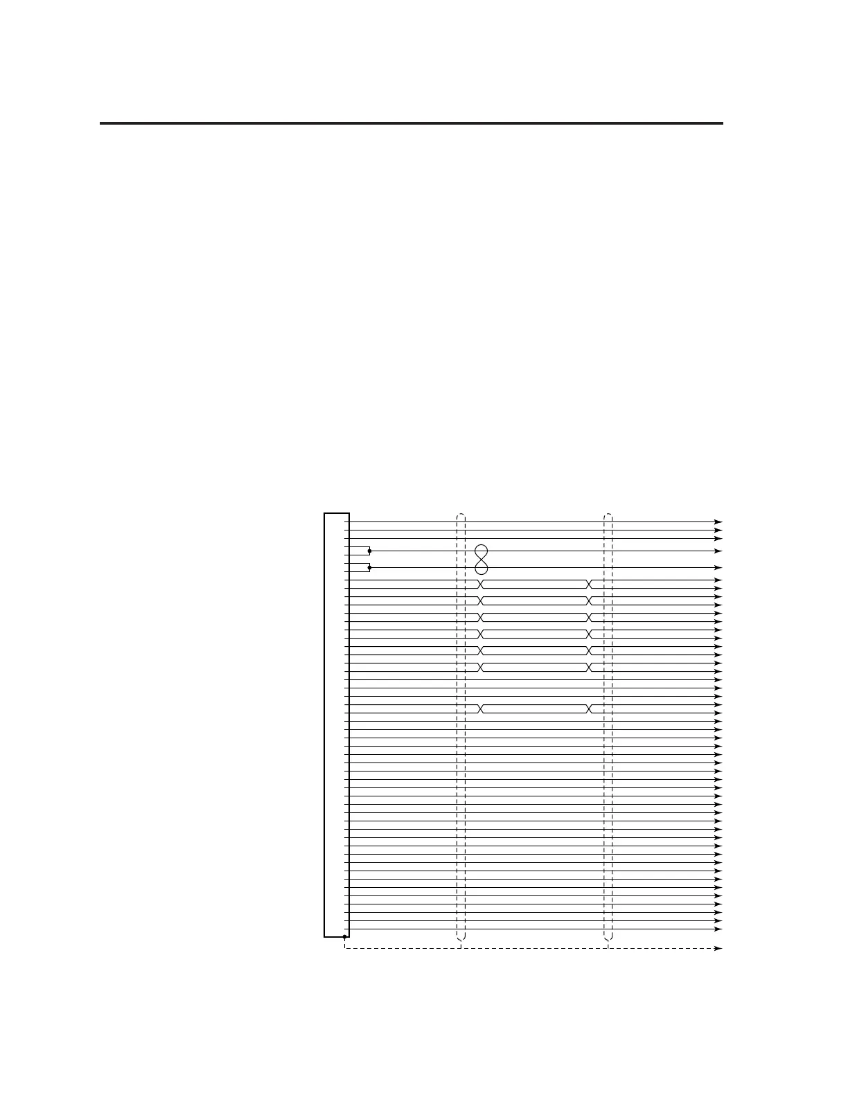
The next drawing shows the color code for the 50 pin connector/flying lead cable.
Shield
White/Violet
White/Gray
Red/Black
White/Black/Orange
White/Black/Green
Green/Black
Yellow/Red
Gray/Blue
Yellow/Green
Gray/Orange
Blue/Red
Blue/Orange
Gray
Pink
White/Pink
Orange/Black
White/Black/Blue
Yellow/Blue
Yellow/Orange
Blue/Yellow
Violet
White/Black/Red
Yellow/Black
White/Black/Yellow
Blue/Black
Green/Red
Gray/Green
Gray/White
Yellow/White
Blue/White
Gray/Brown
Yellow/Brown
Red 16 AWG
Black 16 AWG
Black
White/Black
Red
White/Red
Green
White/Green
Orange
White/Orange
Blue
White/Blue
Yellow
White/Yellow
Brown
White/Brown
Black
White/Black
Red
White/Red
Green
White/Green
Orange
White/Orange
Blue
White/Blue
Yellow
White/Yellow
Brown
White/Brown
1
2
3
4
5
6
7
8
9
10
11
12
13
14
15
16
17
18
19
20
21
22
23
24
25
26
27
28
29
30
31
32
33
34
35
36
37
38
39
40
41
42
43
44
45
46
47
48
49
50
Gemini
Enable
Digital Ground
Reset
reserved
reserved
Digital Ground
Digital Ground
reserved
reserved
reserved
reserved
reserved
reserved
Step+ Out
Step– Out
Direction+ Out
Direction– Out
reserved
reserved
Digital Ground
Analog Output A
Analog Output B
reserved
reserved
Analog Ground
VINref
CNTRL-P: 1 – 3
Input 1
Input 2
Input Ground
Input 3
Input Ground
CNTRL-P: 4 – 8
Input 4
Input 5
Input Ground
Input 6
Input 7
Input 8
Input Ground
Output 1
Output Ground
Output 2
Output Ground
Output 3
Output 4
Output Ground
Output 5
Output 6
Output Ground
Cable – Flying Leads

 Loading...


