Appendix A – Specifications
61
Gemini 50 Pin Connector to 50 Pin D-Connector Cable
Use this cable to connect the Gemini drive’s 50 pin DRIVE I/O connector to the
50 pin D-connector on the Gemini 50 pin breakout module (GEM-VM50).
Part Number: 71-016945-03
CE Cable: Yes, if installed according to instructions in
Appendix C
This cable has the same pinout and color code as the flying lead cable; instead of
flying leads, it has a 50 pin D-connector on the end.
Gemini GEM-VM50 – 50 Pin Breakout Module
Use the 50 pin breakout module for access to individual terminals on the 50 pin
DRIVE I/O connector. The GEM-VM50 includes the cable above.
Description: Part Number:
50 pin Breakout Module (with Cable) GEM-VM50
50 pin Breakout Module (without cable) 01-016986-01
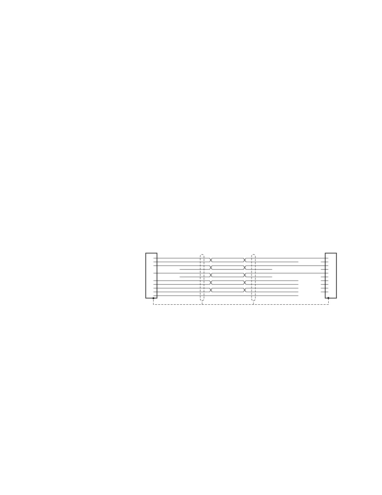
Null Modem Cable – 9 Pin D-Connector to 9 Pin D-Connector
Use this cable for RS-232 communications between the Gemini drive and a
terminal. Note that this is not a “straight-through” cable; pins 2 and 3 are crossed,
making it a “null-modem” cable.
Part Number: 71-016939-10
CE Cable: Yes, if installed according to instructions in
Appendix C
Connector: 9 pin female D-subminiature connector on each end
Shield
Black
Red
Green
Yellow
Gray
Brown
Blue
Violet
Red
Gray
Brown
Blue
Violet
White
Orange
White
Orange
Red
N/C
N/C
N/C
N/C
N/C
N/C
N/C
x
x
x
x
x
x
x
x
x
x
Black
Green
Yellow
5
6
3
2
1
7
4
8
9
5
6
2
1
3
4
7
8
9
Cable – RS-232 Null Modem

 Loading...


