Chapter 2 – Installation
15
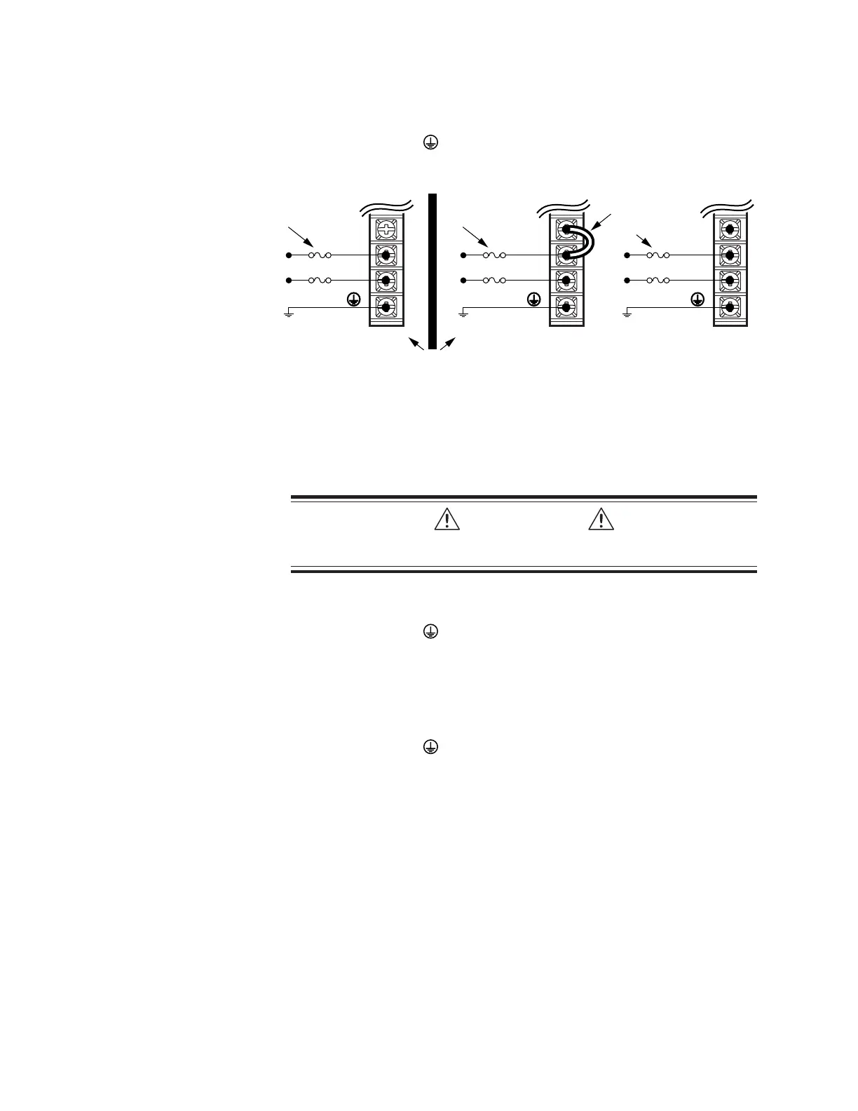
120VAC Operations:
1. Connect power system’s safety earth to drive’s protective conductor terminal,
marked with the symbol. Do not fuse the protective conductor terminal.
2. Connect 120VAC, 50/60 Hz, single phase power line to drive’s L1 and N terminals.
3. Reinstall the clear plastic terminal cover after you make connections.
GT6-L5/8 GT6-U5/8
95 – 132VAC
V DBL
L2/N
L1
95 – 132VAC
Fuses
Connect jumper for
120VAC operations
N/C
N
L1
Fuses
Drive terminals: #8 (M4).
Mating terminals: spade fork, 0.325" maximum width.
V DBL
L2/N
L1
190 – 264VAC
Fuses
Power Connections
GT6-U5 and GT6-U8 AC Power Connections
Connections are illustrated in the drawing above, on the right.
CAUTION
Do not operate GT6-U5/8 in the 132VAC – 190VAC range, or the drive will be
permanently damaged.
120VAC Operations:
1. Connect power system’s safety earth to drive’s protective conductor terminal,
marked with the symbol. Do not fuse the protective conductor terminal.
2. Connect a short jumper between V DBL and L2/N. Use insulated wire for the
jumper, 18 AWG (0.75 mm
2
) or thicker diameter; keep the wire as short as possible.
3. Connect 120VAC, 50/60 Hz, single phase power to drive’s L1 and L2/N terminals
4. Reinstall the clear plastic terminal cover after you make connections.
240VAC Operations:
1. Connect power system’s safety earth to drive’s protective conductor terminal,
marked with the symbol. Do not fuse the protective conductor terminal.
2. Verify there is no jumper between V DBL and L2/N.
3. Connect 240VAC, 50/60 Hz, single phase power to drive’s L1 and L2/N terminals.
4. Reinstall the clear plastic terminal cover after you make connections.
Applying Power
1. Verify that the load is not connected to the motor, and that the motor is clamped
securely in place.
2. Verify that a cable is not attached to the DRIVE I/O connector.
3. Apply power to the drive. The LEDs should display the following states:
Left LED Right LED Indicated State
red off initial power applied
off yellow drive initializing
red off drive ready, not enabled
Proceed to Configuring the Drive.
 Loading...


