76
Gemini GT6 Hardware Installation Guide
System Installation
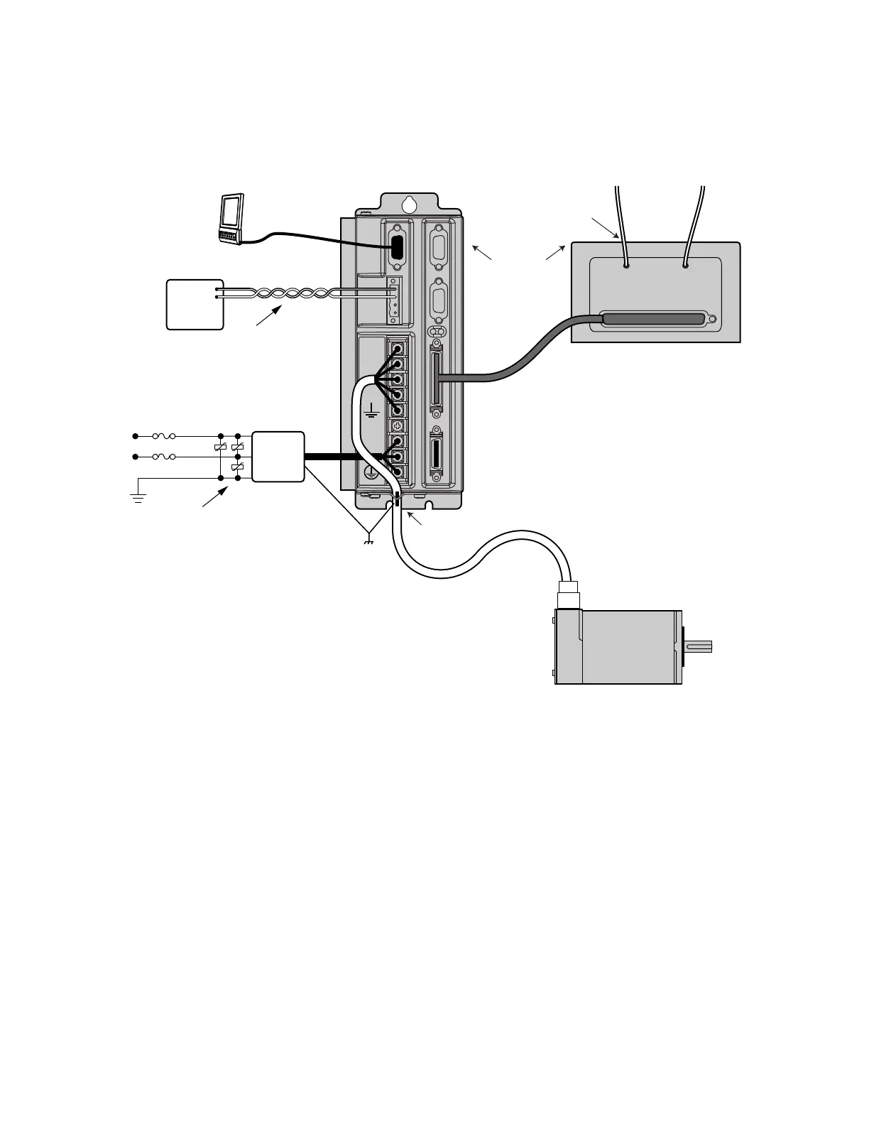
The next figure shows a typical EMC installation.
Twisted at 3 twists
minimum per
inch (25 mm)
Mount to earthed
metal panel, paint
removed from
mounting locations
Saddle clamp
braid; make loop
as short as
possible
Bond braid to earthed panel.
Use R-clamp or bulkhead
clamshell clamp. (See
360° bonding drawing.)
I/O Limits
Varistor
(3 places)
GEM-VM50
Breakout Module
(enclosure mounted, or
not accessible to user)
RS-232/485
Cable
Drive I/O Cable
Gemini
Drive
HPC
N or L2/N
L1
Earth
VAC
VDC+
VDC–
+24VDC
Power
Supply
Mains
Filter
Motor
Cable
Motor
EMC Installation
If you mount the Gemini drive in an enclosure, terminate cable braids (screens) at
the entrance of the enclosure. However, the motor braid must be returned to the
drive’s saddle clamp, not any other location.
 Loading...


